Peripheral Installation
Music-on-Hold (MOH)/ Background Music (BGM) Options
12-8
Strata DK I&M 6/00
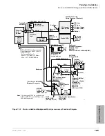
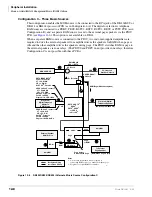
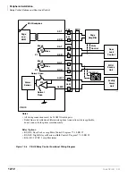
Configuration C – Three Music Sources
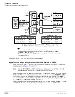
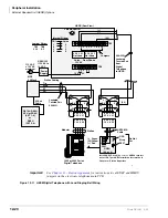
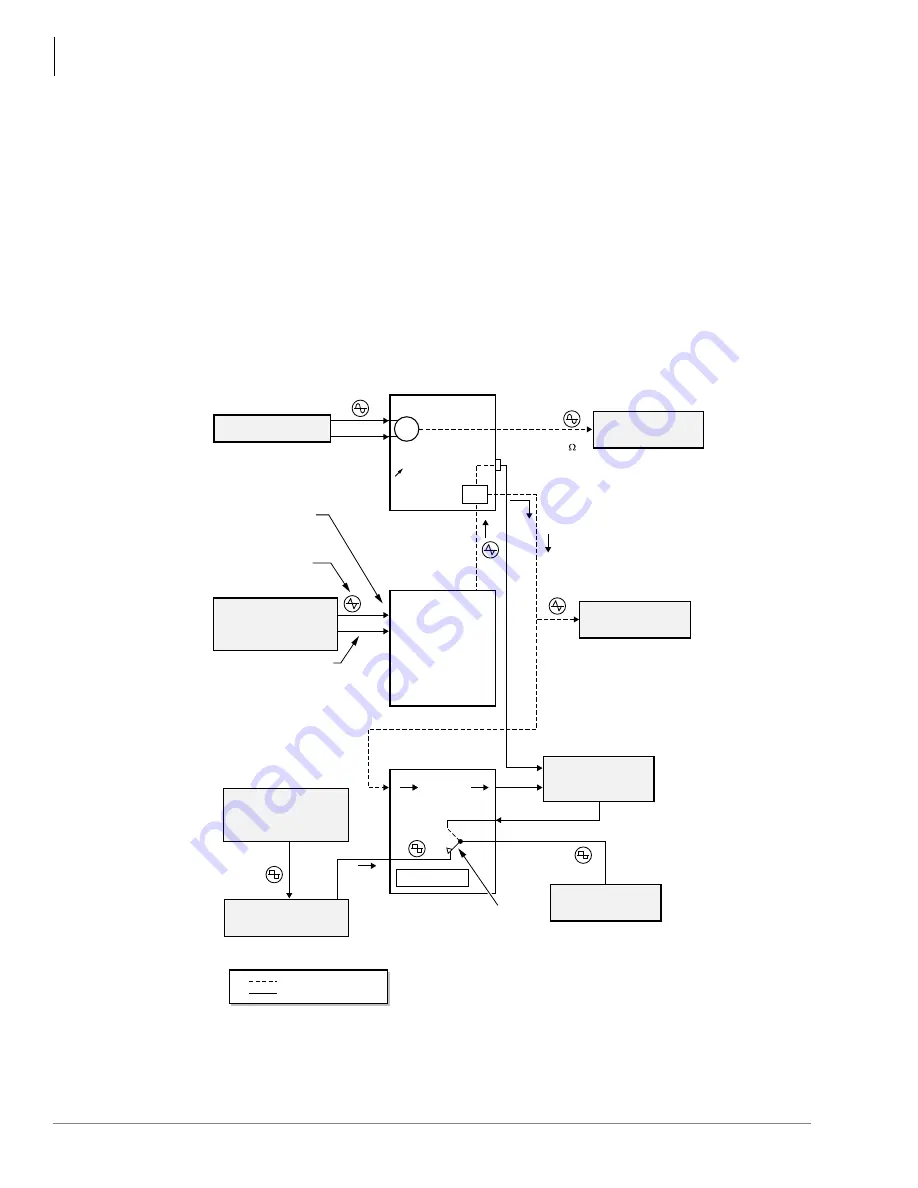
This configuration enables the MOH source to be connected to the RCA jack of the DK40i KSU or
DK424 or DK424i processor PCB (as in Configuration A). The digital or electronic telephone
BGM source is connected to a PEKU, PESU, KSTU2, RSTU, RSTU2, RDSU or PSTU PCB (as in
Configuration B), and a separate BGM source is sent to the external page speakers via the PIOU
PCB (see
). This option is not available on DK14.
When a separate BGM source is connected to the PIOU, two customer-supplied amplifiers are
required to drive the external speakers.One amplifier drives the speakers for BGM when page is
idle and the other amplifier drives the speakers during page. The PIOU switches BGM or page to
the external speakers via zone relays. (The PIOUS and PEPU do not provide zone relays; therefore
Configuration C is not possible with these PCBs.)
Figure 12-6
DK40i/DK424/DK424i Alternate Music Source Configuration C
CO Lines and
Stations On-Hold
MOH
VT
VR
VR1 (Volume)
MOH SOURCE
Electronic/
Digital Telephone
Alternate
BGM Source
BGM/Page (DK424 backplane)
KSU BGM 600
RCA Jack
Electronic/Digital
Telephone Speaker
External Speaker
BGM Source
Amplifier
PIOU Only
P23
600
Ω
(BGM When Page is Idle)
Zone Relays
Activate with Page
Backplane Wiring
Installation Wiring
Page
(BGM: #481 On/#480 Off)
Page
Page
or BGM
BGM
BGM
PEKU 25-Pair Connector
VT = P30, W-S
VR = P5, S-W
Slot XX2, Circuit 3
Cut W5 on PEKU
Program 10, LED 09/On
* KSTU2, RSTU
1
,
RDSU
1
,
PSTU
1
, PESU
1
,
or PEKU
in Slot XX
2
PESU 25-Pair Connector
1
VT = P40, BK-S
VR = P15, S-BK
Slot XX2, Circuit 8
Cut W7 on PESU
Program 10, LED 10/On
RSTU/RDSU/PSTU
1
25 Pair Connector
VT = 28, W-GN
VR = 3, GN-W
SLOT XX2, Circuit 2
RCA Jack
DK14/DK40i
KSU or RCTU
Notes
1. An isolation transformer may be required if
connecting BGM source to a standard telephone port.
2. Program 19 assigns BGM Slot number.
Amplifier
To External
Page Speaker
4300
Summary of Contents for Strata AirLink DK40i
Page 22: ...Introduction Related Documents Media xx Strata DK I M 6 00 ...
Page 48: ...DK14 Installation DK14 Wiring Diagrams 1 26 Strata DK I M 6 00 ...
Page 220: ...DK424 Installation Remote Cabinet Installation Instructions 5 68 Strata DK I M 6 00 ...
Page 262: ...DK424i Configuration Primary Reserve Power Cabinet Hardware 6 42 Strata DK I M 6 00 ...
Page 450: ...Universal Slot PCB Wiring Option Interface PCB Wiring Diagrams 10 42 Strata DK I M 6 00 ...
Page 592: ...Peripheral Installation Enhanced 911 Service E911 12 84 Strata DK I M 6 00 ...
Page 616: ...ACD Installation Spectrum Electronic Wall Boards 13 24 Strata DK I M 6 00 ...
Page 634: ...Fault Finding Fault Isolation Flowcharts 14 18 Strata DK I M 6 00 ...
Page 704: ...ISDN Interfaces ISDN Disconnect Cause Code 16 54 Strata DK I M 6 00 ...

