Peripheral Installation
Music-on-Hold (MOH)/ Background Music (BGM) Options
Strata DK I&M 6/00
12-9
Pe
ri
p
h
er
a
l In
st
al
la
ti
on
➤
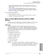
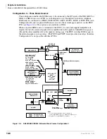
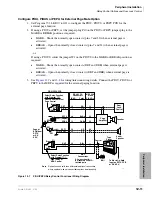
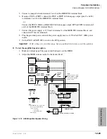
To install the MOH/BGM as BGM
1. Ensure that the MOH option is installed in accordance with
To install the MOH option on Page
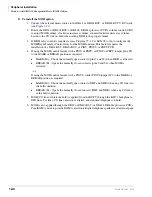
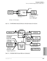
2. The output of the RCTU page/BGM control is applied through the backplane to the output
select switch (SW4) on the PIOU or PEPU. Set the SW4 switch to either SPO or SPI, as
required:
♦
SPO – Directs external page and non-amplified BGM to the HESB or external amplifier
(pins 13 and 38).
♦
SPI – Directs external page and BGM through the on-board 3-watt amplifier to the
external speaker output (pins 25 and 50).
Note
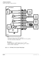
The PIOUS provides non-amplified BGM/page output only (SPT and SPR).
See
.
3. When using an HESB or external amplifier for paging/BGM, adjust volume using the HESB
or amplifier volume control.
4. When using the internal amplifier for paging/BGM, adjust the volume using the volume
control (VR1) on the PIOU/PEPU PCB.
Alternate BGM Source Installation
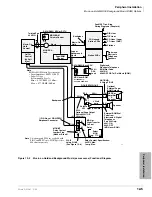
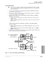
A BGM source can be connected to a station PCB (QSTU2, KSTU2, RSTU2/PSTU, RDSU,
PEKU, or PESU) to send music to all electronic/digital telephone speakers and to the external page
system via a PIOU, PIOUS, or PEPU. The BGM source is separate from the MOH source
connected to the DK424 or DK424i processor PCB. An isolation transformer is needed to connect
a music source to one of the above standard telephone circuits (see
➤
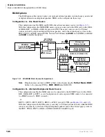
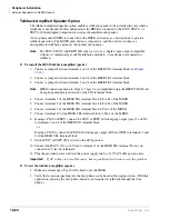
To connect the BGM source to the QSTU2, KSTU2, RSTU2/PSTU, RDSU, PEKU or PESU
See
and follow these steps:
1. Access Program 10-2. If the BGM source is connected to circuit 3 on a PEKU, set LED 09 to
On. If the source is connected to circuit 8 on a PESU, set LED 10 to On. If connecting BGM to
QSTU2, KSTU2, RSTU2, RDSU or PSTU, LED 09 and 10 should be Off.
2. Using Program 19, identify (assign) the BGM slot.
3. If connecting the BGM source to a PEKU or PESU: Connect the PEKU tip and ring of circuit
03 to the 600 ohms or 8 ohms output of the BGM source or connect the BGM output to circuit
8 of a PESU.
...or
If connecting the BGM source to a QSTU2, KSTU2, RSTU2/PSTU or RDSU: Connect circuit
2 of the RSTU2/PSTU or RDSU to a customer-supplied isolation transformer and BGM
source.
Note
The isolation transformer protects the BGM source from potentially damaging QSTU2,
KSTU2, RSTU2/PSTU or RDSU voltage. Some music sources which are designed for
telephone system applications may have this protection built-in and do not require the
transformer. (Consult the documentation provided with the music source.)
4. If the BGM source is connected to either a W5 on the PEKU or W7 on the PESU PCB, cut the
strap. There is no strap to cut on the QSTU2/KSTU2, RSTU2/PSTU or RDSU.
Summary of Contents for Strata AirLink DK40i
Page 22: ...Introduction Related Documents Media xx Strata DK I M 6 00 ...
Page 48: ...DK14 Installation DK14 Wiring Diagrams 1 26 Strata DK I M 6 00 ...
Page 220: ...DK424 Installation Remote Cabinet Installation Instructions 5 68 Strata DK I M 6 00 ...
Page 262: ...DK424i Configuration Primary Reserve Power Cabinet Hardware 6 42 Strata DK I M 6 00 ...
Page 450: ...Universal Slot PCB Wiring Option Interface PCB Wiring Diagrams 10 42 Strata DK I M 6 00 ...
Page 592: ...Peripheral Installation Enhanced 911 Service E911 12 84 Strata DK I M 6 00 ...
Page 616: ...ACD Installation Spectrum Electronic Wall Boards 13 24 Strata DK I M 6 00 ...
Page 634: ...Fault Finding Fault Isolation Flowcharts 14 18 Strata DK I M 6 00 ...
Page 704: ...ISDN Interfaces ISDN Disconnect Cause Code 16 54 Strata DK I M 6 00 ...

