Peripheral Installation
PC/Data Communications Interface Units
12-54
Strata DK I&M 6/00
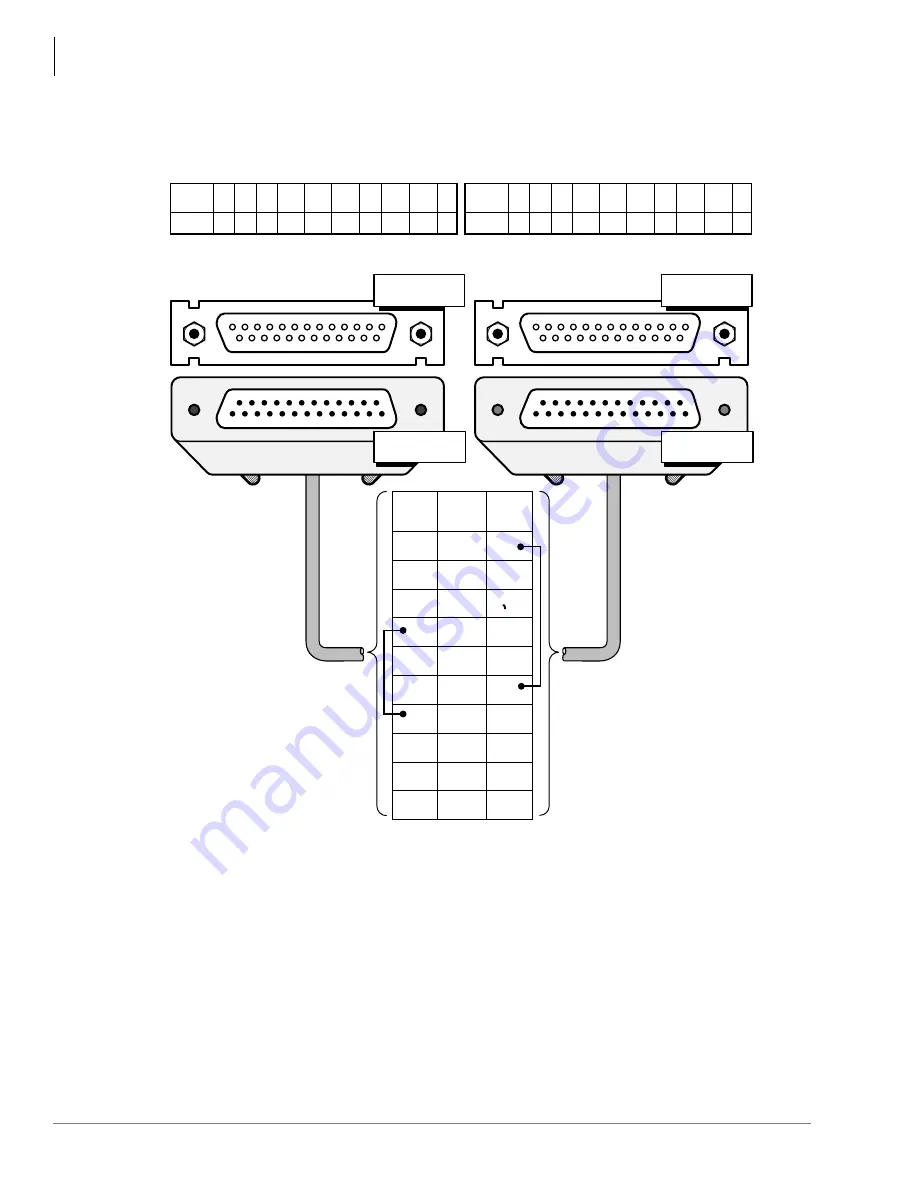
Figure 12-28 PDIU-DS to Hayes-Type Smart Modem, RS-232 Connector/Cable Connections
1
2
3
4
5
6
7
8
5
20
22
1
2
3
4
5
6
7
8
20
22
20
20
22
1
2
3
4
6
7
8
5
1
2
3
4
6
7
8
22
PDIU-DS
Pin#
Name
1
FG
3
RD
4
RTS
5
CTS
6
DSR
7
SG
8
DCD
20
DTR
22
RI
2
TD
Modem
Pin #
Name
1
FG
3
RD
4
RTS
5
CTS
6
DSR
7
SG
8
DCD
20
DTR
22
RI
2
TD
(Open)
(Open)
Hayes-Compatible Smart Modem
(Functions like a DCE)
PDIU-DS
(Configured in the "Connect to
Modem" Mode, P1 ~ P9 = B-C,
So it functions like a DTE)
DB25 Female
Connector
DB25 Female
Connector
DB25 Male
Connector
DB25 Male
Connector
Rear view of modem DB25
connector
Rear view of PDIU-DS DB25, connector
DB25
Pin #
8
3
2
20
7
6
4
5
22
1
Name
DCD
RD
TD
DTR
SG
DSR
RTS
CTS
RI
FG
DB25
Pin #
8
3
2
20
7
6
4
5
22
1
RS-232 Cable
1530
(50 ft. max., 24 AWG,
customer-supplied)
For PDIU-DS port:
Program 20: LEDs 01, 04, 17
ON. All other LEDs OFF. LED
02 should be set ON after the
AT commands
The following commands
should be sent to the modem:
ATS0=1: Auto Answer
ATE0: Disable character echo in
command state
ATQ0: Modem returns result codes
AT&C1: Track presence of data
carrier
AT&D2: Hang up and assume
command state with DTR on
to off transition
Notes
●
Modem receives data on pin 2 (TD) and transmits data on pin 3 (RD).
●
The PDIU-DS must be in the Connect to Modem mode (P1~P9 strapped B-C) so that it transmits data on
pin 2 (TD) and receives data on pin 3 (RD).
●
For the above cable modifications, modem AT commands, and Program 20 settings are required for
proper call release when modems disconnect. With this configuration, the PDIU-DS “READY” light will not
light until modems at both ends establish communication (DCD is detected).
Summary of Contents for Strata AirLink DK40i
Page 22: ...Introduction Related Documents Media xx Strata DK I M 6 00 ...
Page 48: ...DK14 Installation DK14 Wiring Diagrams 1 26 Strata DK I M 6 00 ...
Page 220: ...DK424 Installation Remote Cabinet Installation Instructions 5 68 Strata DK I M 6 00 ...
Page 262: ...DK424i Configuration Primary Reserve Power Cabinet Hardware 6 42 Strata DK I M 6 00 ...
Page 450: ...Universal Slot PCB Wiring Option Interface PCB Wiring Diagrams 10 42 Strata DK I M 6 00 ...
Page 592: ...Peripheral Installation Enhanced 911 Service E911 12 84 Strata DK I M 6 00 ...
Page 616: ...ACD Installation Spectrum Electronic Wall Boards 13 24 Strata DK I M 6 00 ...
Page 634: ...Fault Finding Fault Isolation Flowcharts 14 18 Strata DK I M 6 00 ...
Page 704: ...ISDN Interfaces ISDN Disconnect Cause Code 16 54 Strata DK I M 6 00 ...


