DK40i Configuration
Configuration Considerations
Strata DK I&M 6/00
2-15
DK40i Conf
iguration
Configuration Considerations
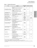
The following considerations should be taken into account when filling out the tables in
“Worksheet 1 – System PCB Assignment Guide” on Page 2-11
Base Cabinet
1. Only one line PCB (TCOU, TDDU, TBSU or TBUU) can be installed in the Base cabinet.
2. If TBSU or TBUU is installed, each circuit can be configured independently as a station side
or line side BRI circuit.
3. Each TBSU or TBUU ISDN BRI circuit uses two station ports and no line numbers if the
circuit is configured for the station side.
4. Each TBSU or TBUU ISDN BRI circuit will use two line numbers and no station ports if the
circuit is configured for the line side.
5. TDDU provides four DID lines and does not use station ports.
6. Install TCIU2 for Base KSU CO (TCOU) Caller ID Lines.
CAUTION!
To prevent system malfunction, do not install TCIU1 in the DK40i system.
7. K5RCU, K5RCU2 or K4RCU3 must be installed when using built-in automated attendant
(AA), ACD, ACD/MIS, Voice Mail, ABR, Stratagy DK, standard telephone ports, Tie lines,
DISA, or DID Lines.
8. KKYS1~3 is required for built-in AA; KKYS2 for AA and ACD; KKYS3 for AA, ACD/MIS.
9. TSIU can be used for an RS-232 Maintenance (TTY) port, SMDI, ACD/MIS or SMDR port.
RSIU cannot be used.
Expansion Cabinet
1. Each RDDU provides four DID lines and does not use station ports. This is different from the
DK40 and DK16e in which each DID circuit used a line number and station port.
2. Each REMU to PEMU provides the four Tie lines and does not use station ports. This is
different from the DK40 and DK16e in which each Tie line circuit used a line number and
station port.
3. Stratagy DK can be installed in the expansion unit to provide two, four, six or eight built-in
Automated Attendant/Voice Mail circuits. Always install Stratagy DK in slot 15, 16, or 17; do
not
install Stratagy DK in slot 18. Program the Stratagy VM ports as if they were standard
telephone ports connected to an external VM device. All models of Stratagy DK use up eight
station ports.
4. Install RCIU2/RCIS in
slot 17 (only)
for Expansion KSU (RCOU/RCOS or RGLU2) Caller
ID Lines.
CAUTION!
To prevent system malfunction, do no install RCIU1 in DK40i, and RCIU2
must
not
be installed in slot 18.
5. If required, install PIOU, PIOUS, and RSSU in any slot.
Summary of Contents for Strata AirLink DK40i
Page 22: ...Introduction Related Documents Media xx Strata DK I M 6 00 ...
Page 48: ...DK14 Installation DK14 Wiring Diagrams 1 26 Strata DK I M 6 00 ...
Page 220: ...DK424 Installation Remote Cabinet Installation Instructions 5 68 Strata DK I M 6 00 ...
Page 262: ...DK424i Configuration Primary Reserve Power Cabinet Hardware 6 42 Strata DK I M 6 00 ...
Page 450: ...Universal Slot PCB Wiring Option Interface PCB Wiring Diagrams 10 42 Strata DK I M 6 00 ...
Page 592: ...Peripheral Installation Enhanced 911 Service E911 12 84 Strata DK I M 6 00 ...
Page 616: ...ACD Installation Spectrum Electronic Wall Boards 13 24 Strata DK I M 6 00 ...
Page 634: ...Fault Finding Fault Isolation Flowcharts 14 18 Strata DK I M 6 00 ...
Page 704: ...ISDN Interfaces ISDN Disconnect Cause Code 16 54 Strata DK I M 6 00 ...

