DK40i Installation
MDF Wiring Diagrams
Strata DK I&M 6/00
3-43
D
K
40
i Installation
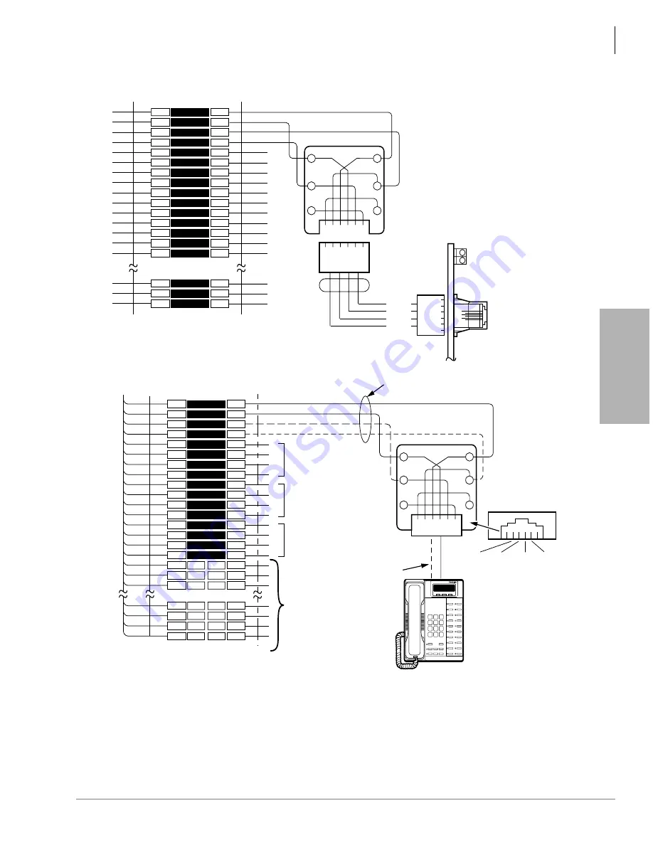
Figure 3-26 MDF Wiring to CO Lines and Digital Telephones (KCDU)
1
2
3
4
5
6
7
8
9
10
11
12
13
14
15
16
17
18
19
47
48
49
50
1
2
3
4
5
6
7
8
9
10
11
12
13
14
15
16
17
18
19
47
48
49
50
W-BL
BL-W
W-O
O-W
W-GN
GN-W
W-BR
BR-W
W-S
S-W
R-BL
BL-R
R-O
O-R
R-GN
GN-R
R-BR
BR-R
R-S
V-BR
BR-V
V-S
S-V
26
1
27
2
28
3
29
4
30
5
31
6
32
7
33
8
34
9
35
49
24
50
25
BRIDGING
CLIPS
TO KCDU
W/FEMALE CONNECTOR
25-PAIR CABLE W/MALE AMP CONNECTOR
66M150 SPLIT BLOCK
CIRCUIT 2 TO DKT2
OR PDIU-DS
CIRCUIT 3 TO DKT3
OR PDIU-DS
CIRCUIT 4 TO DKT4
OR PDIU-DS
(-) T1 (VOICE/DATA)
(GND) R1 (VOICE/DATA)
(-) PT1 (ADD, POWER)
(GND) PR1 (ADD. POWER)
T2
R2
PT2
PR2
T3
R3
PT3
PR3
T4
R4
PT4
PR4
NOT USED
JACKETED TWISTED PAIRS
24AWG (1 OR 2 PAIR, SEE NOTE 2)
STATION CABLING
GN
6 5 4 3 2 1
Y
BL
R
BK
W
R1
PT1
T1
PR1
RJ11
DIGITAL
TELEPHONE
(WITH OR WITHOUT
PDIU-DI/PDIU-DI2) OR
PDIU-DS
- or -
DDCB
2- OR 4-WIRE
MODULAR CORD
TO RJ11 JACK
ON BOTTOM
OF PDIU-DI
GND
PR (5)
(-)
T (4)
GND
R (3)
(-)
PT (2)
1
2
3
4
5
6
7
8
9
10
11
12
13
14
15
48
49
50
1
2
3
4
5
6
7
8
9
10
11
12
13
14
15
48
49
50
BRIDGING
CLIPS
66M150 SPLIT BLOCK
GN
6 5 4 3 2 1
Y
BL
R
BK
W
2 3 4 5
MODULAR
CORD
1-6
T1
R1
T2
R2
T1
R1
T2
R2
TO
NETWORK
R1
R2
T1
T2
KCDU
CO2 LED
CO1 LED
CO1+2
MODULAR
JACK
R2
R1
T1
T2
5
4
3
2
KCDU
PIN-OUT
1
2
3
4
5
6
NETWORK JACK: RJ14C
FIC: 02LS2
CO LINE CABLING
Notes
1 Voltage levels:
T, PT = -26.3 ~ 27.8 VDC
R, RP = 0.0 VDC (GND) (Reference to SG ground)
2. T/R wires are always required; PT/PR are additional power wires required only for long station runs or when operating on
reserve power per
. PT/PR may be used with normal station runs also.
3. ADMs and/or DIUs can be connected to circuits 1 ~ 4, DDCB can be connected to Circuit 1.
Summary of Contents for Strata AirLink DK40i
Page 22: ...Introduction Related Documents Media xx Strata DK I M 6 00 ...
Page 48: ...DK14 Installation DK14 Wiring Diagrams 1 26 Strata DK I M 6 00 ...
Page 220: ...DK424 Installation Remote Cabinet Installation Instructions 5 68 Strata DK I M 6 00 ...
Page 262: ...DK424i Configuration Primary Reserve Power Cabinet Hardware 6 42 Strata DK I M 6 00 ...
Page 450: ...Universal Slot PCB Wiring Option Interface PCB Wiring Diagrams 10 42 Strata DK I M 6 00 ...
Page 592: ...Peripheral Installation Enhanced 911 Service E911 12 84 Strata DK I M 6 00 ...
Page 616: ...ACD Installation Spectrum Electronic Wall Boards 13 24 Strata DK I M 6 00 ...
Page 634: ...Fault Finding Fault Isolation Flowcharts 14 18 Strata DK I M 6 00 ...
Page 704: ...ISDN Interfaces ISDN Disconnect Cause Code 16 54 Strata DK I M 6 00 ...


