Strata DK I&M 6/00
4-1
DK424 Configur
at
ion
DK424 Configuration
4
This chapter explains how to configure the Strata DK424 system. The system has a modular
design which enables it to support a number of station and CO line configurations. The main
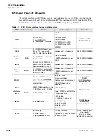
component of the system is the common control unit (RCTU) Printed Circuit Board (PCB).
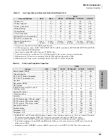
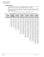
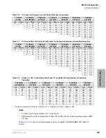
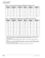
The focus of this chapter is a series of worksheets, providing a systematic procedure for
determining the system’s size. The worksheets also provide space to record the hardware and
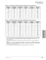
station devices that make up the system. Tables and example worksheets are included to assist you
in filling out the worksheets.
Important!
Prior to Release 4.0, Tie and DID lines used station ports. With Release 4.0 and
higher processors, these lines do not use station ports, allowing larger capacity
systems when Tie and DID lines are required.
System Configuration
Important!
System Configuration can be complex and time consuming. For best results:
●
Use DKQuote to provide easy, fast, automated configuration. See the DKQuote User Guide
for more information.
●
If you do not have DKQuote, use the Worksheets in this chapter.
The DK424’s main components are: the DK424 Base Cabinet (DKSUB424), DK424 Expansion
Cabinets (DKSUE424), and four system processors (RCTUA4, RCTUBA3/BB4, RCTUC3/D4,
and RCTUE3/F4). The processor used in the system depends on the features and number of
telephones and CO lines required. Each cabinet is shipped with its required Power Supply
(RPSU280); the same power supply used in DK280 cabinets.
See
Chapter 4 – DK424 Configuration
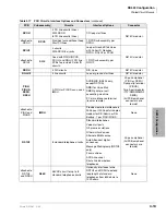
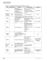
for detailed information on installing RCTU PCBs.
Summary of Contents for Strata AirLink DK40i
Page 22: ...Introduction Related Documents Media xx Strata DK I M 6 00 ...
Page 48: ...DK14 Installation DK14 Wiring Diagrams 1 26 Strata DK I M 6 00 ...
Page 220: ...DK424 Installation Remote Cabinet Installation Instructions 5 68 Strata DK I M 6 00 ...
Page 262: ...DK424i Configuration Primary Reserve Power Cabinet Hardware 6 42 Strata DK I M 6 00 ...
Page 450: ...Universal Slot PCB Wiring Option Interface PCB Wiring Diagrams 10 42 Strata DK I M 6 00 ...
Page 592: ...Peripheral Installation Enhanced 911 Service E911 12 84 Strata DK I M 6 00 ...
Page 616: ...ACD Installation Spectrum Electronic Wall Boards 13 24 Strata DK I M 6 00 ...
Page 634: ...Fault Finding Fault Isolation Flowcharts 14 18 Strata DK I M 6 00 ...
Page 704: ...ISDN Interfaces ISDN Disconnect Cause Code 16 54 Strata DK I M 6 00 ...


