DK424 Configuration
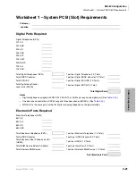
Worksheet 1 – System PCB (Slot) Requirements
4-24
Strata DK I&M 6/00
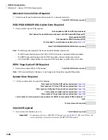
CO Line PCBs/Slots Required
1.
Determine analog loop start line PCB slot requirements.
Total loop start lines (with/ without Caller ID) divided by 8 (round up)
Total RCOU/RCOS PCBs (slots) required
Total loop start lines (with/without Caller ID) divided by 4 (round up)
Total RGLU2/RCOU/PCOU PCBs (slots) required (PCOU existing)
Total analog loop start line PCB slots required
Notes
●
RGLU2 can provide loop or ground start lines.
●
RCOU provides four loop start CO lines in its basic configuration. An RCOS can be attached to
the RCOU to add four more loop start CO lines for a total of eight per slot.
●
PCOU2 provides four loop start CO lines.
●
The PCOU1 and the PCOU2 are identical in fit, form, and function for the U.S. market.
2. Determine analog ground start line PCB slot requirements.
Total ground start lines (with/without Caller ID) divided by 4 (round up)
Total analog ground start line PCB slots required
Note
RGLU2 provides four CO lines that can be
individually configured as loop start or ground start.
3. Determine E911 CAMA line PCB slot requirements.
Total RMCU/RCMS CAMA PCBs (1 slot) required (RMCU existing)
Note
The RMCU supports two subassemblies (RCMS) that provide a total of up to four ports.
4. Determine Caller ID (FSK) receiver/decoder PCB slot
requirements.
Total loop and ground start lines (with Caller ID) divided by 8 (round up)
Total RCIU2/RCIS PCB slots required
Note
RCIU2 provides four caller ID receiver/decoder circuits. RCIU2 with RCIS subassembly provides
eight caller ID receiver/decoder circuits. Always use RCIU2 with RCIS for up to eight circuits as
opposed to using two RCIU PCBs. These circuits do not use up station port or CO line software
assignments.
5. Determine analog Tie line PCB slot requirements.
Total analog Tie lines (with or without ANI/DNIS) divided by 4
Total REMU/PEMU PCB slots required
Summary of Contents for Strata AirLink DK40i
Page 22: ...Introduction Related Documents Media xx Strata DK I M 6 00 ...
Page 48: ...DK14 Installation DK14 Wiring Diagrams 1 26 Strata DK I M 6 00 ...
Page 220: ...DK424 Installation Remote Cabinet Installation Instructions 5 68 Strata DK I M 6 00 ...
Page 262: ...DK424i Configuration Primary Reserve Power Cabinet Hardware 6 42 Strata DK I M 6 00 ...
Page 450: ...Universal Slot PCB Wiring Option Interface PCB Wiring Diagrams 10 42 Strata DK I M 6 00 ...
Page 592: ...Peripheral Installation Enhanced 911 Service E911 12 84 Strata DK I M 6 00 ...
Page 616: ...ACD Installation Spectrum Electronic Wall Boards 13 24 Strata DK I M 6 00 ...
Page 634: ...Fault Finding Fault Isolation Flowcharts 14 18 Strata DK I M 6 00 ...
Page 704: ...ISDN Interfaces ISDN Disconnect Cause Code 16 54 Strata DK I M 6 00 ...

