DK424 Configuration
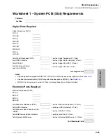
Worksheet 3 – System PCB Assignment Guide
4-28
Strata DK I&M 6/00
Worksheet 3 – System PCB Assignment Guide
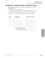
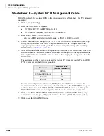
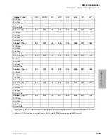
Fill in Worksheet 3 by recording PCBs in the following order (see Worksheet 1 for PCB type and
quantities):
1. Write in the Cabinet Type.
2. Enter the RCTU PCBs as required:
♦
RCTUBA, RCTUC, or RCTUE in slot R11
♦
RCTUA, RCTUBB, RCTUD, or RCTUF in slot RCTU
3. Enter PDKU, PEKU, or RSIU in slot 11.
...and/or if an RSIU is installed in slot 11, install a PDKU or PEKU in slot 12.
4. Starting with the lowest empty slot (S12 or S13), record all station, attendant console, loop
start, ground start PCBs from lower to higher numbered slots (left to right). Record the
appropriate port numbers used by each. Do not leave empty slots except when installing
RDTU PCBs (see
5. After all station, attendant console, and ground/loop start line PCBs are recorded, write in all
DID and Tie line PCBs starting from the first numbered empty slot to the highest needed (in
left to right order). Record the line numbers. Do not leave empty slots except when installing
RDTU PCBs.
The maximum number of station ports used by station, PC attendant console, Tie, and DID
PCBs can not exceed the following quantities:
In some rare configurations, when using RDTU (T1) Tie or DID lines in systems, the
maximum number of stations allowed may be reduced because the RDTU PCB takes up two
or three cabinet slots. Each RDTU, REMU, or RDDU Tie/DID line uses one station port.
RCIU/RCIS PCBs do not use station ports or CO line software time slot assignments.
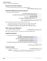
6. Write in the PIOU, PIOUS, PEPU, RSSU, RCIU2/RCIS and RCIU2/RCIS PCBs in any
convenient vacant slot, preferably in the last slots. Record any Caller ID circuit numbers.
7. Write in any Interface PCB Options.
Processor
Maximum Ports
(Station, Tie and DID)
RCTUA
32
RCTUB or RCTUBA/BB
80
RCTUC/D
240
RCTUE/F
336
Summary of Contents for Strata AirLink DK40i
Page 22: ...Introduction Related Documents Media xx Strata DK I M 6 00 ...
Page 48: ...DK14 Installation DK14 Wiring Diagrams 1 26 Strata DK I M 6 00 ...
Page 220: ...DK424 Installation Remote Cabinet Installation Instructions 5 68 Strata DK I M 6 00 ...
Page 262: ...DK424i Configuration Primary Reserve Power Cabinet Hardware 6 42 Strata DK I M 6 00 ...
Page 450: ...Universal Slot PCB Wiring Option Interface PCB Wiring Diagrams 10 42 Strata DK I M 6 00 ...
Page 592: ...Peripheral Installation Enhanced 911 Service E911 12 84 Strata DK I M 6 00 ...
Page 616: ...ACD Installation Spectrum Electronic Wall Boards 13 24 Strata DK I M 6 00 ...
Page 634: ...Fault Finding Fault Isolation Flowcharts 14 18 Strata DK I M 6 00 ...
Page 704: ...ISDN Interfaces ISDN Disconnect Cause Code 16 54 Strata DK I M 6 00 ...

