DK424 Installation
AC Power and Grounding Requirements
Strata DK I&M 6/00
5-29
DK424 Installa
tion
AC Power and Third Wire Ground Test
Test each “third wire ground” separately for continuity by either measuring the resistance between
the third prong terminal (earth ground) and a metal cold water pipe (maximum: 1 ohm) or by using
a commercially available earth ground indicator. If neither procedure is possible, perform the
following procedure.
➤
To test each “third wire ground” for continuity
1. Obtain suitable voltmeter, and set it for a possible reading of up to 250VAC.
2. Connect the meter probes between the two main AC voltage terminals (white and black wires)
on the wall outlet. The reading obtained should be between 100~125VAC.
3. Move one of the meter probes to the third terminal (green wire ground, point A in
and
). Either the same reading or a reading of zero volts should be obtained.
4. If the reading is zero volts, leave one probe on the ground terminal and move the other probe
to the second voltage terminal.
CAUTION!
If a reading of zero volts is obtained on both voltage terminals (white wire to
green wire, black wire to green wire), the outlet is not properly grounded. Omit
Steps 5 and 6, and proceed directly to Step 7.
5. If a reading of zero volts on one terminal and a reading of 100~125VAC on the other terminal
is obtained, remove both probes from the outlet.
6. Set the meter to the “OHMS/Rx1” scale. Place one probe on the ground terminal, and the other
probe on the terminal that produced a reading of zero volts. The reading should be less than
one ohm.
CAUTION!
If the reading is more than one ohm, then the outlet is not adequately grounded.
If the above tests show the outlet AC voltage is not in range or is not properly
grounded, the condition should be corrected (per Article 250 of the National
Electrical Code) by a qualified electrician before the system is connected.
➤
To test the frame ground conductor for continuity
1. Disconnect the AC plug(s) of the system to make sure that the separate earth ground paths are
separated.
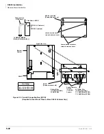
2. With a suitable volt/ohm meter, perform a reading between points “A” and “B” shown in
. Verify that the readings do not exceed the figures listed below. If
they do, the condition must be corrected by a qualified electrician before the system is
connected.
A to B: 1 volt maximum then A to B: 1 ohm maximum
WARNING!
Hazardous voltages that may cause death or injury are exposed during the
following test. Use great care when working with AC power line voltage.
WARNING!
Hazardous voltages that may cause death or injury are exposed during the
following test. Use great care when working with AC power line voltage.
Summary of Contents for Strata AirLink DK40i
Page 22: ...Introduction Related Documents Media xx Strata DK I M 6 00 ...
Page 48: ...DK14 Installation DK14 Wiring Diagrams 1 26 Strata DK I M 6 00 ...
Page 220: ...DK424 Installation Remote Cabinet Installation Instructions 5 68 Strata DK I M 6 00 ...
Page 262: ...DK424i Configuration Primary Reserve Power Cabinet Hardware 6 42 Strata DK I M 6 00 ...
Page 450: ...Universal Slot PCB Wiring Option Interface PCB Wiring Diagrams 10 42 Strata DK I M 6 00 ...
Page 592: ...Peripheral Installation Enhanced 911 Service E911 12 84 Strata DK I M 6 00 ...
Page 616: ...ACD Installation Spectrum Electronic Wall Boards 13 24 Strata DK I M 6 00 ...
Page 634: ...Fault Finding Fault Isolation Flowcharts 14 18 Strata DK I M 6 00 ...
Page 704: ...ISDN Interfaces ISDN Disconnect Cause Code 16 54 Strata DK I M 6 00 ...


