DK424 Installation
Reserve Power Installation
Strata DK I&M 6/00
5-43
DK424 Installa
tion
Note
AC/DC wiring and conduit “A” and “B” must be installed by a licensed electrician per
local electrical code (conduit trade size is 1/2 inch).
See
for battery specifications and wiring guidelines.)
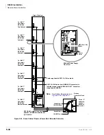
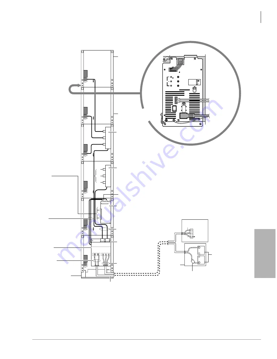
Figure 5-27 Reserve Power/AC Wiring for Three to Six Cabinets (Floor Mount)
TO
RPSU1
+ –
+ –
TO
RPSU2
TO
RPSU3
TO
RPSU4
TO
RPSU5
TO
RPSU6
BATT
PSU
+ –
BATT AC120V
L N FG
A
B
A
B
1
6
•
•
•
FG
+
+
–
–
12 VOLT
12 VOLT
L
N
11.5 AMP
MAX
AC CIRCUIT
BREAKER
TO
BUILDING
GROUND
FI
(Maximum configuration: Cabinet 1 (top) ~ Cabinet 6 (bottom) right-hand side view)
Right Side View
RBTCIA-1.5M Battery
Cables, One to
Each Power Supply
BATT Connector
(6-max)
RCCB to RBDB
Battery Connecting
Cables/Connectors
are Factory Wired on
RCCB
RCCB 1A, AC/DC
Conduit
Connection Box
(Shown mounted with
cover off)
12-AWG Wire
(Minimum)
RFMF, Floor
Mount Fixture
14 AWG Wire
(Minimum)
L = Line Wire (Hot)
N = Neutral Wire
FG = Ground Wire
AC Receptacles
AC Power Cords/Plugs
from RPSB No. 1 and No. 2
RBDB1A, Battery
Distribution/
Fuse Box (Shown mounted
with cover on)
RCCB to RBDB Cable/Connector
RPSB - AC Power
Strip No. 2 (3 receptacles)
for cabinet (4~6) power supplies
RPSB - AC Power
Strip No. 1
(3 receptacles)
for cabinet (1~3)
power supplies
Cabinet 1
Building Main
Electrical
Distribution Panel
F1 = 24 AMP
Fuse
12 Volt Batteries
Battery
Cabinet or
Rack
1
2
3
-24V
POWER
+5V
-5V
AC IN
FG
DC OUT
+
-
ON
OFF
BATT
RPSU280 Power Supply
Front View
Cabinet 2 (etc)
RBTCIA-1.5M
Cable from
RBDB
AC Cord
from
RPSB
DKSUB
➜
DKSUE
➜
1472
Summary of Contents for Strata AirLink DK40i
Page 22: ...Introduction Related Documents Media xx Strata DK I M 6 00 ...
Page 48: ...DK14 Installation DK14 Wiring Diagrams 1 26 Strata DK I M 6 00 ...
Page 220: ...DK424 Installation Remote Cabinet Installation Instructions 5 68 Strata DK I M 6 00 ...
Page 262: ...DK424i Configuration Primary Reserve Power Cabinet Hardware 6 42 Strata DK I M 6 00 ...
Page 450: ...Universal Slot PCB Wiring Option Interface PCB Wiring Diagrams 10 42 Strata DK I M 6 00 ...
Page 592: ...Peripheral Installation Enhanced 911 Service E911 12 84 Strata DK I M 6 00 ...
Page 616: ...ACD Installation Spectrum Electronic Wall Boards 13 24 Strata DK I M 6 00 ...
Page 634: ...Fault Finding Fault Isolation Flowcharts 14 18 Strata DK I M 6 00 ...
Page 704: ...ISDN Interfaces ISDN Disconnect Cause Code 16 54 Strata DK I M 6 00 ...


