DK424 Installation
RCTUA, RCTUBA/BB, RCTUC/D, RCTUE/F Common Control Units
5-46
Strata DK I&M 6/00
Hardware Options
Some PCBs must be configured for hardware options prior to installation of the PCB in the
cabinet. Configuration instructions for internal hardware options are provided in the individual
PCB installation procedures in this chapter. Configuration instructions for external hardware
options are provided in Chapter 12 – Peripheral Installation.
Software Options
PCBs are configured for software options through programming, following the installation
instructions of the PCBs. A programming overview for each PCB is provided in the individual
PCB installation procedures in this chapter. Refer to the
Strata DK Programming Manual
for
detailed programming instructions.
RCTUA, RCTUBA/BB, RCTUC/D, RCTUE/F
Common Control Units
System:
DK424 Base Cabinet
Current Version:
RCTUA3, RCTUBA3/BB4, RCTUC3/D4, RCTUE3/F4
Older Version(s):
RCTUA1, RCTUB1&2, RCTUC/D1&2, RCTUBB3, RCTUD3, RCTUF3
The common control unit provides centralized control for the system. It incorporates a 16 or 32 bit,
68000-type microprocessor and contains a custom time switch and conference Large Scale
Integration (LSI) circuitry.
The processor operating software is programmed on four read-only-memory (ROM) chips on the
RCTUA3 or RCTUA4, BB3 or BB4, and D3 or D4 PCBs and on the Flash Memory PCB RMMS
on the RCTUF3 or F4 PCBs. The operating software (ROM or RMMS) is factory-installed.
The RCTU PCBs also provide busy tone detection as a standard feature for Auto Busy Redial
(ABR) and interfaces with optional RRCS DTMF receivers, feature keys (RKYS1, 2, or 3) for
Auto Attendant (AA), Automatic Call Distribution (ACD), Management Information System
(MIS) for ACD, Toshiba proprietary RS-232 and SMDI voice mail interfaces.
ACD and attendant consoles requires the RCTUBA/BB, RCTUC/D and RCTUE/F processors.
Important!
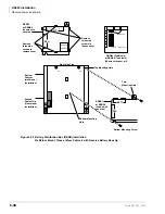
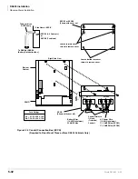
When installing RCTUE/F, you must remove the Motherboard Jumper Unit (MBJU)
from the DK424 Base Cabinet (between R11 and RCTU slot on the front side of the
cabinet motherboard), see
to locate MBJU. If installing an RCTUA, BA/
BB, C/D, the MBJU must be installed on the DK424 Base Unit.
PCB Installation Power Supply Considerations
1. The power supply must be Off whenever removing or installing the common control unit—
RCTUA, RCTUBA/BB, RCTUC/D and RCTUE/F (see
).
2. It is recommended that the power supply be Off, whenever possible, when removing or
installing the other PCBs.
Summary of Contents for Strata AirLink DK40i
Page 22: ...Introduction Related Documents Media xx Strata DK I M 6 00 ...
Page 48: ...DK14 Installation DK14 Wiring Diagrams 1 26 Strata DK I M 6 00 ...
Page 220: ...DK424 Installation Remote Cabinet Installation Instructions 5 68 Strata DK I M 6 00 ...
Page 262: ...DK424i Configuration Primary Reserve Power Cabinet Hardware 6 42 Strata DK I M 6 00 ...
Page 450: ...Universal Slot PCB Wiring Option Interface PCB Wiring Diagrams 10 42 Strata DK I M 6 00 ...
Page 592: ...Peripheral Installation Enhanced 911 Service E911 12 84 Strata DK I M 6 00 ...
Page 616: ...ACD Installation Spectrum Electronic Wall Boards 13 24 Strata DK I M 6 00 ...
Page 634: ...Fault Finding Fault Isolation Flowcharts 14 18 Strata DK I M 6 00 ...
Page 704: ...ISDN Interfaces ISDN Disconnect Cause Code 16 54 Strata DK I M 6 00 ...


