DK424 Installation
RCTUA, RCTUBA/BB, RCTUC/D, RCTUE/F Common Control Units
Strata DK I&M 6/00
5-49
DK424 Installa
tion
Music-on-hold/Background Music Volume Control (External Options)
Each of the common control units (except RCTUBB, RCTUD and RCTUF) has a trim
potentiometer (VR1) to adjust the volume of the MOH/BGM source connected to the Music-on-
hold (MOH)/Background Music (BGM) RCA jack interface, which is also on the common control
unit. The volume control potentiometer and the MOH/BGM interface are on the RCTUA,
RCTUBA3, RCTUA4, RCTUC, RCTUE3 and RCTUE4 PCBs.
The VR1 potentiometer does not control the volume of alternate BGM sources connected to either
the RSTU2, RDSU, PSTU, PEKU, PESU, or other BGM source interfaces.
➤
To install the MOH/BGM source to common control unit
➤
Adjust the VR1 potentiometer to the desired volume level while listening to MOH or BGM
(see Chapter 12 – Peripheral Installation).
RRCS
The DTMF receiver subassembly (RRCS) translates DTMF signals to data signals and attaches to
common control units with 4, 8, or 12 receiver circuits.
RRCS (4, 8, or 12) Installation onto RCTUA
➤
Mate RRCS connectors J1, J2, J3, and J4 (
) with RCTUA connectors P2, P3, P4,
P5. Apply firm, even pressure to the RRCS to ensure proper mating of the connectors.
RRCS Installation onto RCTUBA, RCTUC/D, and RCTUE/F
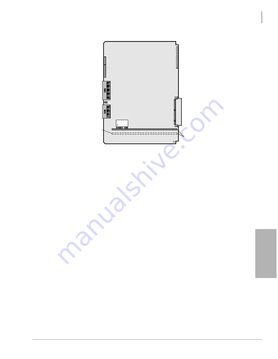
RCTUBA provides up to 12 DTMF receiver circuits because an RRCS PCB can be installed on
RCTUBA only and not on RCTUBB.
Backplane
Connector
TOSHIBA
RKYS_A
RCTU A, B, BB, D or F
CBRUK1A
(Soldered on RCTU)
RCTUD
Only
1956
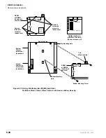
Figure 5-30 RKYS Feature Key Installation
Summary of Contents for Strata AirLink DK40i
Page 22: ...Introduction Related Documents Media xx Strata DK I M 6 00 ...
Page 48: ...DK14 Installation DK14 Wiring Diagrams 1 26 Strata DK I M 6 00 ...
Page 220: ...DK424 Installation Remote Cabinet Installation Instructions 5 68 Strata DK I M 6 00 ...
Page 262: ...DK424i Configuration Primary Reserve Power Cabinet Hardware 6 42 Strata DK I M 6 00 ...
Page 450: ...Universal Slot PCB Wiring Option Interface PCB Wiring Diagrams 10 42 Strata DK I M 6 00 ...
Page 592: ...Peripheral Installation Enhanced 911 Service E911 12 84 Strata DK I M 6 00 ...
Page 616: ...ACD Installation Spectrum Electronic Wall Boards 13 24 Strata DK I M 6 00 ...
Page 634: ...Fault Finding Fault Isolation Flowcharts 14 18 Strata DK I M 6 00 ...
Page 704: ...ISDN Interfaces ISDN Disconnect Cause Code 16 54 Strata DK I M 6 00 ...


