DK424i Configuration
Worksheet 6: DK424i Cabinet Slot Configuration
Strata DK I&M 6/00
6-27
DK424i Configuration
Worksheet 6: DK424i Cabinet Slot Configuration
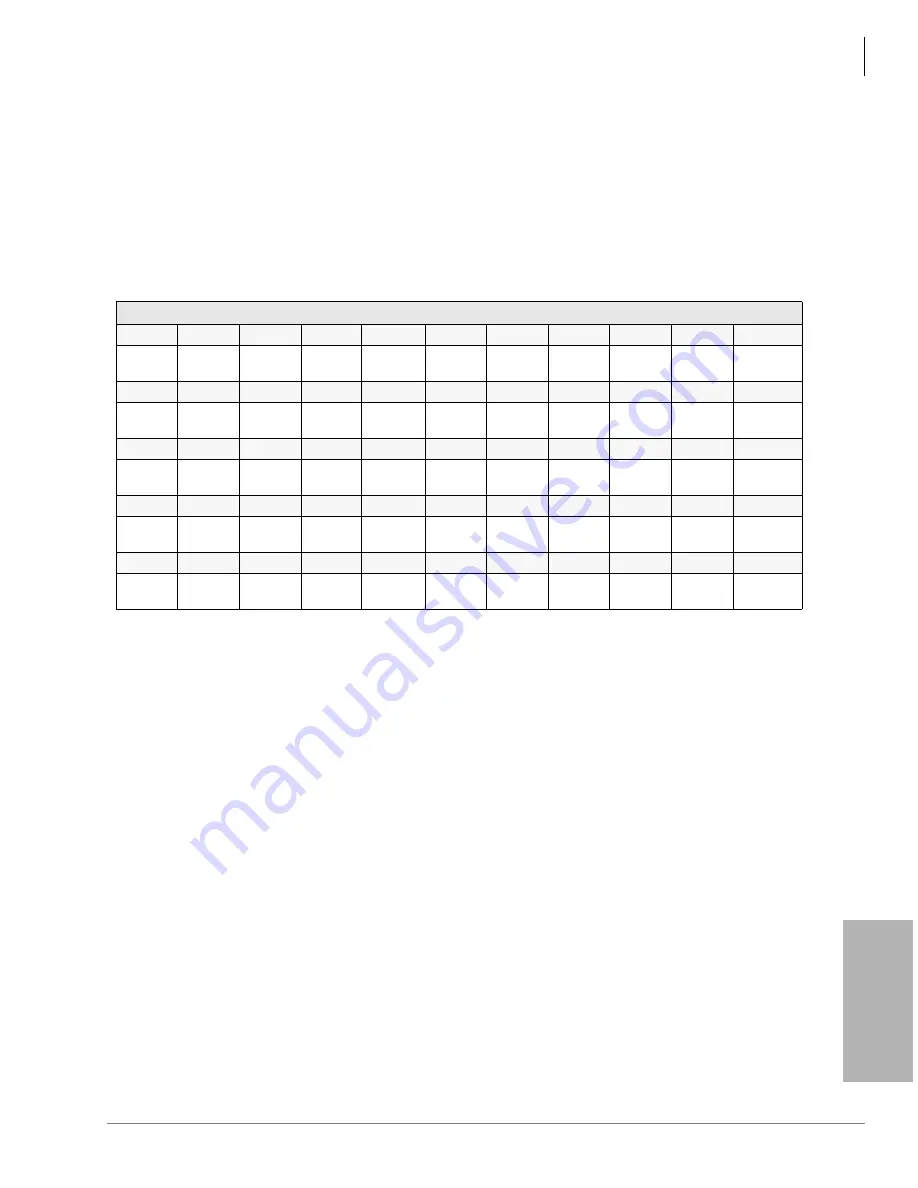
The cabinet diagram below enables you to write in the PCBs installed in each cabinet slot. Use the
PCB placement guideline below to place PCBs in the correct slots. Fill in the PCBs that go into
each slot from the PCB quantities determined in the worksheets on the previous pages and the
information provided in this worksheet. After completing Worksheet 6, Worksheet 7 must be
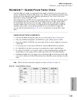
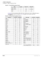
completed to verify that the cabinet power factors do not exceed 85.
PCB Placement Guidelines
Station, line and option PCBs can be mixed in cabinets in any pattern. Do not skip slots except for
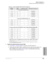
vacant slots that provide RDTU, RPTU, or RWIU capacity as shown in
. Toshiba
recommends placing RSIU, RRCU, RDTU, RPTU, and/or RWIU PCBs, as needed, first because
they have special placement rules.
After all PCBs are placed in cabinets, the processor PCB that meets the requirements of the
configuration can be selected. Use the numbered step sequence as a guide, beginning with
“1. Programming Telephone Interface”
.
Main Location _______________ Remote Location 1___ 2___ 3___ 4____
DK424i Cabinet Slots
Base
B101
1
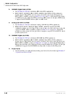
1. B101/B102 – processor slots: S101 - RSIU, PDKU, or PEKU slot.
B102
1
S101
1
S102
S103
2
S104
S105
2
2. RDTU, RPTU, and RWIU (up to 16 handsets) allowed slots. The adjacent slot must be vacant to reach maximum capacity.
S106
S107
2
S108
PCB
Type
Cab 2
S201
3
3. RWIU slots for up to 32 handsets. Up to three adjacent slots must be vacant to reach maximum capacity.
4. Speaker OCA/DIU Data Slots: All slots in Base Cabinet and S_01~S_06 in all Expansions Cabinets.
5. For details, see the guidelines below.
S202
S203
2
S204
S205
2
S206
S207
3
S208
S209
S210
PCB
Type
Cab 3
S301
2
S302
S303
2
S304
S305
2
S306
S307
3
S308
S309
S310
PCB
Type
Cab 4
S401
2
S402
S403
2
S404
S405
2
S406
S407
3
S408
S409
S410
PCB
Type
Cab 5
S501
2
S502
S503
2
S504
S505
2
S506
S507
3
S508
S509
S510
PCB
Type
Summary of Contents for Strata AirLink DK40i
Page 22: ...Introduction Related Documents Media xx Strata DK I M 6 00 ...
Page 48: ...DK14 Installation DK14 Wiring Diagrams 1 26 Strata DK I M 6 00 ...
Page 220: ...DK424 Installation Remote Cabinet Installation Instructions 5 68 Strata DK I M 6 00 ...
Page 262: ...DK424i Configuration Primary Reserve Power Cabinet Hardware 6 42 Strata DK I M 6 00 ...
Page 450: ...Universal Slot PCB Wiring Option Interface PCB Wiring Diagrams 10 42 Strata DK I M 6 00 ...
Page 592: ...Peripheral Installation Enhanced 911 Service E911 12 84 Strata DK I M 6 00 ...
Page 616: ...ACD Installation Spectrum Electronic Wall Boards 13 24 Strata DK I M 6 00 ...
Page 634: ...Fault Finding Fault Isolation Flowcharts 14 18 Strata DK I M 6 00 ...
Page 704: ...ISDN Interfaces ISDN Disconnect Cause Code 16 54 Strata DK I M 6 00 ...


