DK424i Installation
Step 6: Remote Expansion Cabinet Unit
Strata DK I&M 6/00
7-57
DK424i Ins
tal
lation
Table 7-21
RRCU Controls
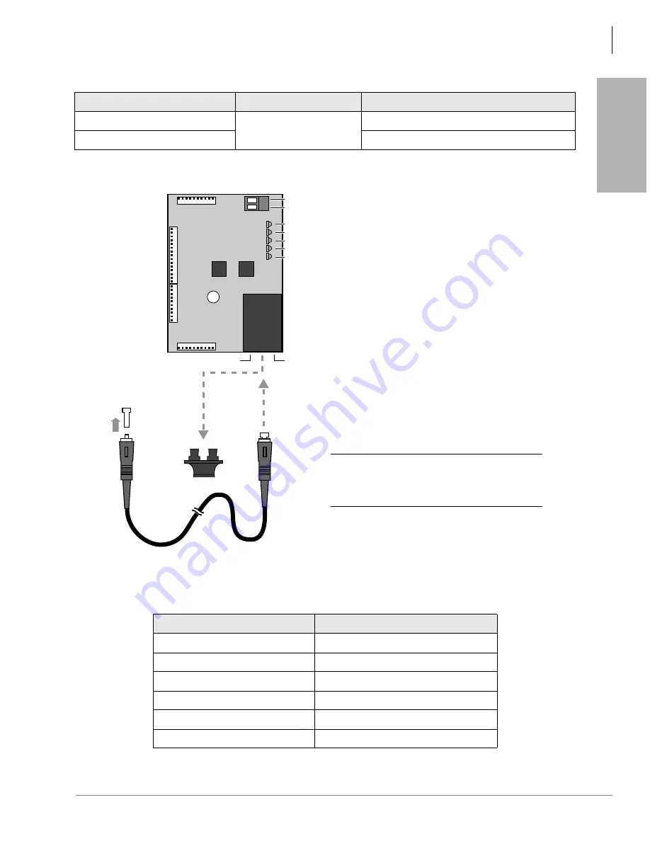
The ROMS subassembly and fiber optic cable connectors is shown in
lists
the fiber optic cable specifications.
Figure 7-37 ROMS1A Subassembly
Control/Indicator/Connector
Type of Component
Description
Jumper Plug P10
3-terminal Jumper Plug
Master Mode (M connections)
Jumper Plug P10
Slave Mode (S connections)
Table 7-22
Fiber Optic Specification
Item
Specification
Transmission Speed
155.52 Mbps
Optical Source
LED, 1300 nm
Fiber Type
Multi-mode, Graded Index Fiber (GIF)
Core Diameter
62.5 micrometers
Cladding Diameter
125 micrometers
Connector Type
SC (2-pin transmit and receive)
TX Side
RX Side
4379
RO
MS1A
SD
RDER
SYCF
SYCS
RST
CD1
CD2
CD3
CD4
CD5
J3
J1
1
15
1
10
J2
J4
1
11
11
1
-24v
DG
PFT-CONTROL
Optical
Module
Plastic
Cap
Remove
Rubber Cap
to plug in
Fiber Optic
Cable
Fiber Optic
Cable
CAUTION!
Inserting the fiber connector
at an angle or too forcefully
can cause damage.
Summary of Contents for Strata AirLink DK40i
Page 22: ...Introduction Related Documents Media xx Strata DK I M 6 00 ...
Page 48: ...DK14 Installation DK14 Wiring Diagrams 1 26 Strata DK I M 6 00 ...
Page 220: ...DK424 Installation Remote Cabinet Installation Instructions 5 68 Strata DK I M 6 00 ...
Page 262: ...DK424i Configuration Primary Reserve Power Cabinet Hardware 6 42 Strata DK I M 6 00 ...
Page 450: ...Universal Slot PCB Wiring Option Interface PCB Wiring Diagrams 10 42 Strata DK I M 6 00 ...
Page 592: ...Peripheral Installation Enhanced 911 Service E911 12 84 Strata DK I M 6 00 ...
Page 616: ...ACD Installation Spectrum Electronic Wall Boards 13 24 Strata DK I M 6 00 ...
Page 634: ...Fault Finding Fault Isolation Flowcharts 14 18 Strata DK I M 6 00 ...
Page 704: ...ISDN Interfaces ISDN Disconnect Cause Code 16 54 Strata DK I M 6 00 ...


