T1
Slot Assignments
Strata DK I&M 6/00
8-5
T1
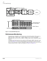
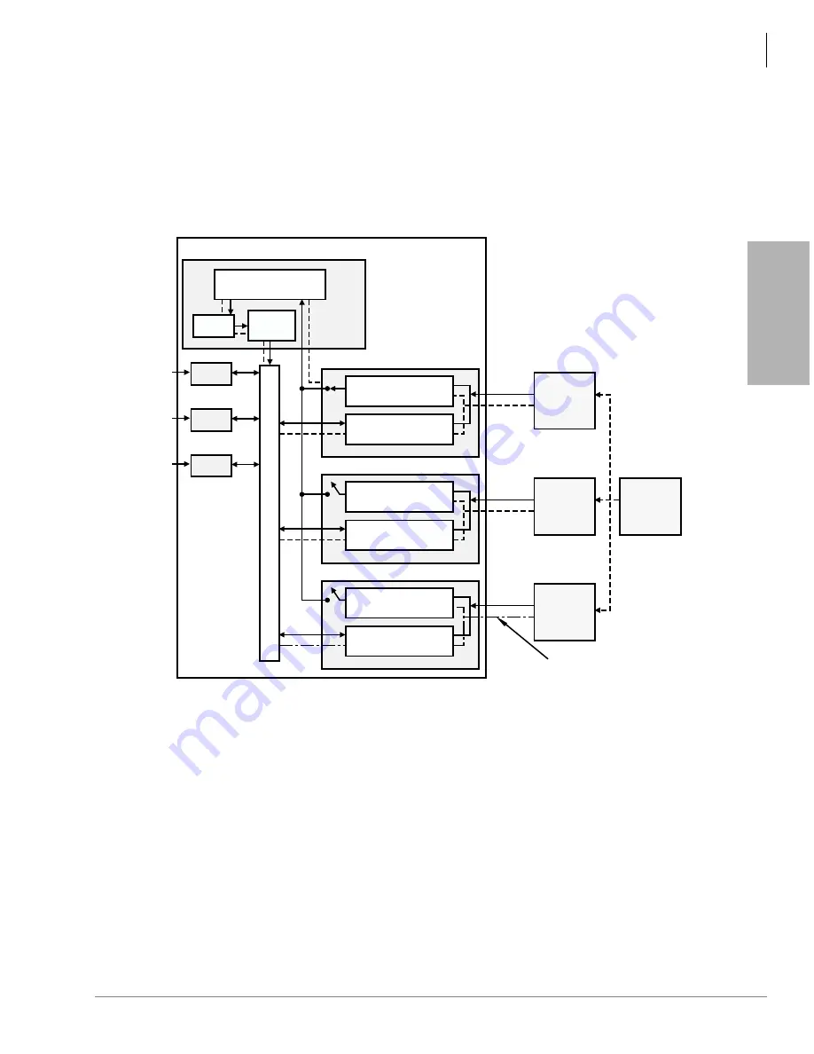
lowest slot number should be assigned as the Primary Reference RDTU (*42-1, DATA = 1
FOR THIS RDTU).
If a malfunction occurs and Primary Synchronization is lost, the DK automatically switches
modes and synchronizes to the T1 span connected to the RDTU PCB designated as the
Secondary Reference (provided that there are two RDTU PCBs installed in the DK) (see
).
If there are two RDTU PCBs installed, it is recommended not to install the Primary and
Secondary Reference RDTU PCBs in the same DK cabinet if possible (although both Primary
and Secondary Reference RDTU PCBs can be installed in the same cabinet). The Secondary
Reference RDTU should also be connected to a Telco or Long Distance Provider T1 span
(*42-2, Data = 2 for this RDTU).
If the equipment on the other end of the DK T1 lines should synchronize to the DK clock
source, then blanks should be entered in Program *42. In this case, the DK clock runs free and
is considered the Master Synchronization provider. The DK can be assigned as the Master
(free run) clock provider if the far end equipment connected to the RDTU T1 span is a
Customer Premise type equipment and it is not synchronized to some other T1 provider (i.e.,
PBX, Channel Bank, Key/Hybrid or other DK). In this case (when the Telco network is not
5236
Synchronization
Circuit
RDTU(2) (Secondary Ref)
Digital Voice Path
Synchronization
Circuit
RDTU(3)
Span
Line 3
T1 Span Clock Not
Synchronized Properly with
Stratum 1 Clock Source
Digital Voice Path
Other
T1
Provider
Span
Line 1
Telco
Central
Office
T1
Span
Line 2
AT&T
Long
Distance
T1
Stratum 1
Clock
Source
RDTU(1) (Primary Ref)
SS
1
SS
2
SS
3
DK Digital Transmission Voice Path
PDKU
Digital
Telephone
PEKU
Electronic
Telephone
RSTU
Standard
Telephone
Strata DK
Processor PCB
Synchronization
Circuit
Clock
Time
Switch
Synchronization
Circuit
Digital Voice Path
Figure 8-1
RDTU Primary/Secondary Reference Block Diagram
Summary of Contents for Strata AirLink DK40i
Page 22: ...Introduction Related Documents Media xx Strata DK I M 6 00 ...
Page 48: ...DK14 Installation DK14 Wiring Diagrams 1 26 Strata DK I M 6 00 ...
Page 220: ...DK424 Installation Remote Cabinet Installation Instructions 5 68 Strata DK I M 6 00 ...
Page 262: ...DK424i Configuration Primary Reserve Power Cabinet Hardware 6 42 Strata DK I M 6 00 ...
Page 450: ...Universal Slot PCB Wiring Option Interface PCB Wiring Diagrams 10 42 Strata DK I M 6 00 ...
Page 592: ...Peripheral Installation Enhanced 911 Service E911 12 84 Strata DK I M 6 00 ...
Page 616: ...ACD Installation Spectrum Electronic Wall Boards 13 24 Strata DK I M 6 00 ...
Page 634: ...Fault Finding Fault Isolation Flowcharts 14 18 Strata DK I M 6 00 ...
Page 704: ...ISDN Interfaces ISDN Disconnect Cause Code 16 54 Strata DK I M 6 00 ...


