T1
Applications
Strata DK I&M 6/00
8-9
T1
5. Run the RDTU self check per
. After self check
passes, put P1 and P2 to the Off position for normal operation and insert the RDTU PCB back
into the appropriate slot.
6. Install CSUs and wire them to the RDTU and Network Interface Unit (NIU) or Customer
Premises T1 circuit as required (see
Note
Before connecting the CSU to the Telco line, notify the T1 provider. You should also
notify the T1 provider before disconnecting the CSU.
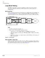
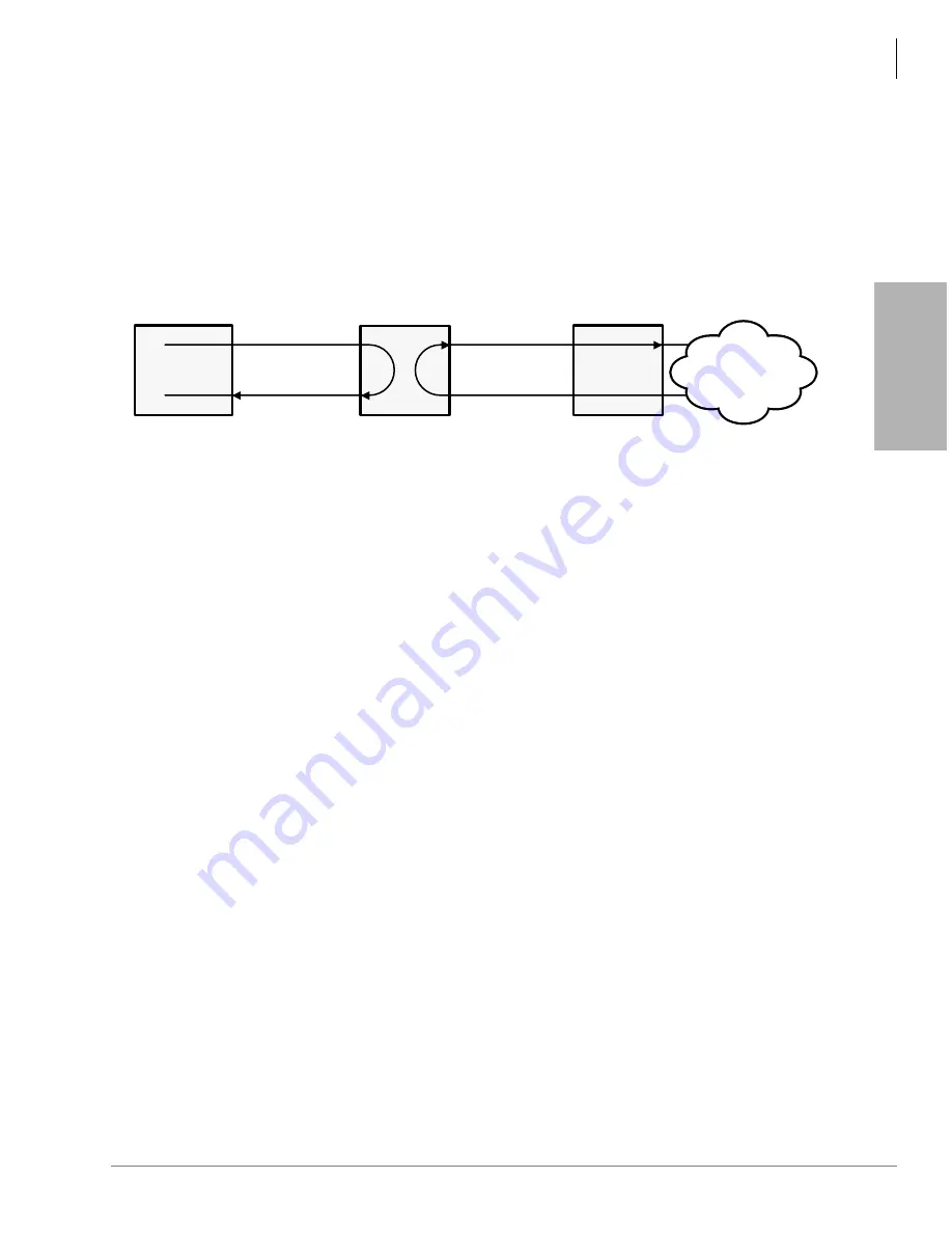
Figure 8-3
CSU Local and Network Loop Back Tests
7. Perform CSU to RDTU and CSU to Network loop back testing per CSU documentation and
Notes
●
Local loop back and network loop back test cannot be performed simultaneously.
●
CSU local/network loop back is a function of the CSU, not all CSUs provide this function –
see CSU I&M documentation for CSU loop back test procedures.
8. After loop back testing is complete and synchronized with the far end T1 circuit, perform test
calls on all RDTU lines. (Use the troubleshooting procedures in
to help correct problems.)
9. Check T1 performance periodically for transmission errors using the “T1ERR” test. This
requires a local or remote maintenance terminal connected to the PIOU or PIOUS PCB (local)
and IMDU or Hayes-compatible modem (remote).
Applications
Each RDTU T1 PCB requires the following connecting equipment and cables to provide service
(see the following sections and
RDTU to Network
If the RDTU must interface to a public telephone network or common carrier T1 circuit, the
RDTU must be connected to a CSU. Use the NDTU cable (30 ft. cable supplied with RDTU) to
connect the RDTU to the CSU. The function of the CSU is to provide the required interface
between the RDTU PCB and the Public Telephone or Carrier Network. The interface created by
the CSU normally provides protection and capabilities for loop back testing both the Network
equipment and the RDTU PCB.
Transmit
Receive
CSU
NIU
Receive
Transmit
Local Loop Back
Network Loop Back
DK RDTU
Network
5237
Summary of Contents for Strata AirLink DK40i
Page 22: ...Introduction Related Documents Media xx Strata DK I M 6 00 ...
Page 48: ...DK14 Installation DK14 Wiring Diagrams 1 26 Strata DK I M 6 00 ...
Page 220: ...DK424 Installation Remote Cabinet Installation Instructions 5 68 Strata DK I M 6 00 ...
Page 262: ...DK424i Configuration Primary Reserve Power Cabinet Hardware 6 42 Strata DK I M 6 00 ...
Page 450: ...Universal Slot PCB Wiring Option Interface PCB Wiring Diagrams 10 42 Strata DK I M 6 00 ...
Page 592: ...Peripheral Installation Enhanced 911 Service E911 12 84 Strata DK I M 6 00 ...
Page 616: ...ACD Installation Spectrum Electronic Wall Boards 13 24 Strata DK I M 6 00 ...
Page 634: ...Fault Finding Fault Isolation Flowcharts 14 18 Strata DK I M 6 00 ...
Page 704: ...ISDN Interfaces ISDN Disconnect Cause Code 16 54 Strata DK I M 6 00 ...


