T1
T1 Fault Isolation
8-18
Strata DK I&M 6/00
➤
To receive the “T1 ERROR DISPLAY” from a terminal (local or remote)
1. Establish communication with the terminal or PC using a communication software (e.g.,
Procomm®).
2. Enter the security code, and press
Enter
(or
Return
).
3. At the
>MODE
prompt, type
DUMP
(must be all caps), press
Enter
(or
Return)
. The
>D
prompt displays on your screen.
4. At the
>D
prompt, type
T1ERR
and press
Enter
(or
Return
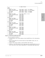
). The display (see
shows all RDTU PCBs (DTUNO=1~DTUNO=8) even if the associated RDTU (1~8) is not
installed. The ERROR counter can only be reset by turning the DK Off and On.
Use
for recording customer’s problems.
➤
To exit the dump mode
➤
At the
>D
prompt, type
QUIT
, press
Enter
(or
Return
); the
>MODE
prompt displays.
T1 Fault Isolation
T1 fault troubleshooting can be complex and may require expensive test equipment to perform the
necessary fault isolation. Because of the high cost, many dealers have not purchased T1 test
equipment. As a result, on a cutover when an RDTU does not synchronize or CO lines simply do
not function, the site technician can only check wiring and cabling. Without proper test equipment,
there is very little that can be tested.
This section provides some procedures that can be done without T1 test equipment to help find the
cause of a failure, or at least determine if system hardware is functioning properly.
The DK also provides T1 “in-service” monitoring which allows maintenance personnel to detect
line errors without introducing any disturbances on the line. This method of testing permits
maintenance personnel to monitor T1 performance without the expense of test equipment or
without taking the T1 circuit out of service. The T1 error check is particularly useful for
monitoring the T1 circuit for intermittent problems that may become more serious as time
progresses (see
“RDTU Performance Monitor Printout”
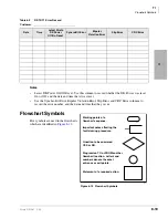
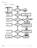
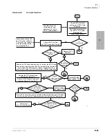
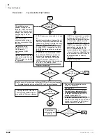
If experiencing problems with an RDTU span circuit, refer to
to isolate the
fault. The flowcharts in this section use the same logic symbols as those used in DK. Document
error information in
Summary of Contents for Strata AirLink DK40i
Page 22: ...Introduction Related Documents Media xx Strata DK I M 6 00 ...
Page 48: ...DK14 Installation DK14 Wiring Diagrams 1 26 Strata DK I M 6 00 ...
Page 220: ...DK424 Installation Remote Cabinet Installation Instructions 5 68 Strata DK I M 6 00 ...
Page 262: ...DK424i Configuration Primary Reserve Power Cabinet Hardware 6 42 Strata DK I M 6 00 ...
Page 450: ...Universal Slot PCB Wiring Option Interface PCB Wiring Diagrams 10 42 Strata DK I M 6 00 ...
Page 592: ...Peripheral Installation Enhanced 911 Service E911 12 84 Strata DK I M 6 00 ...
Page 616: ...ACD Installation Spectrum Electronic Wall Boards 13 24 Strata DK I M 6 00 ...
Page 634: ...Fault Finding Fault Isolation Flowcharts 14 18 Strata DK I M 6 00 ...
Page 704: ...ISDN Interfaces ISDN Disconnect Cause Code 16 54 Strata DK I M 6 00 ...


