Universal Slot PCBs
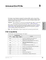
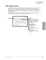
PCB Chapter Layout
Strata DK I&M 6/00
9-3
Universal Slot PCBs
PCB Chapter Layout
Each PCB outline begins with the PCB’s designation and title (the outline appears in the chapter in
alphabetical order by designation). A brief synopsis of the PCB appears next and includes a
notation of the system(s) that the PCB can be used in, the circuits supplied by the PCB, what
equipment the PCB interfaces with, and a list of the PCB’s older version(s) with a brief description
of their differences.
Installation and programming instructions follow the synopsis with a table showing the PCB’s
controls, indicators and connectors and an illustration of the board.
System:
DK16e Expansion KSU, DK424
Circuits per PCB:
four DID lines
Interfaces with:
DID lines
Older Versions:
None
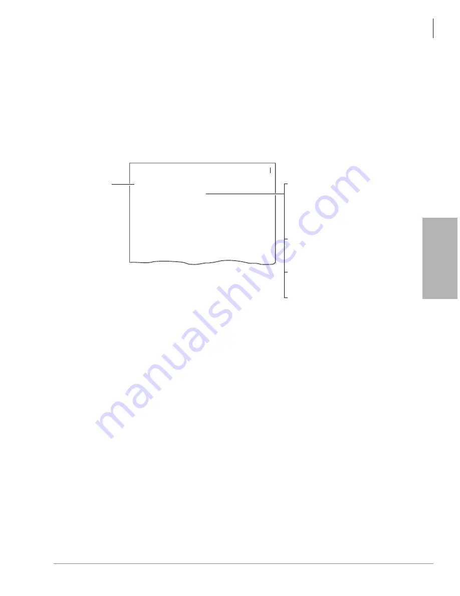
RDDU - Direct Inward Dialing Line Interface Unit
PCB Title
System:
Circuits per PCB:
Gives the type of system that is
compatible with the given PCB. Be
sure to read this information before
attempting to use a PCB with your
system application.
Type and number of circuits
available on the PCB.
Type of line/hardware the PCB can
accept.
Interfaces with:
Describes older version or versions
of the PCB.
Older Version(s):
The RDDU provides four Direct Inward dialing (DID) lines, each of which can have a single
office code along with a block of extensions. If an RDDU is installed, an RRCS must be
installed for DTMF operation, but not for dial pulse operation.
Each extension can be assigned to ring a station [DN] that appears on one or multiple stations,
Distributed Hunt or ACD Group (DK424 only), or an external telephone number selected in
system programming. This enables calls over the same line to be routed to different stations or
group of stations. An extension can also be assigned to ring the maintenance modem. Each
RDDU can be set for either wink start or immediate. All RDDU lines support DNIS and ANI
features.
RDDU controls, indicators and interface connectors are shown in Figure 7-10 and described in
Table 7-8.
RDDU Hardware Option
There are no hardware options supported by the RDDU.
DK40i/DK424 Universal Slot PCBs
PCB Chapter Layout
Summary of Contents for Strata AirLink DK40i
Page 22: ...Introduction Related Documents Media xx Strata DK I M 6 00 ...
Page 48: ...DK14 Installation DK14 Wiring Diagrams 1 26 Strata DK I M 6 00 ...
Page 220: ...DK424 Installation Remote Cabinet Installation Instructions 5 68 Strata DK I M 6 00 ...
Page 262: ...DK424i Configuration Primary Reserve Power Cabinet Hardware 6 42 Strata DK I M 6 00 ...
Page 450: ...Universal Slot PCB Wiring Option Interface PCB Wiring Diagrams 10 42 Strata DK I M 6 00 ...
Page 592: ...Peripheral Installation Enhanced 911 Service E911 12 84 Strata DK I M 6 00 ...
Page 616: ...ACD Installation Spectrum Electronic Wall Boards 13 24 Strata DK I M 6 00 ...
Page 634: ...Fault Finding Fault Isolation Flowcharts 14 18 Strata DK I M 6 00 ...
Page 704: ...ISDN Interfaces ISDN Disconnect Cause Code 16 54 Strata DK I M 6 00 ...


