Universal Slot PCBs
RDTU – T1 Interface Unit
Strata DK I&M 6/00
9-51
Universal Slot PCBs
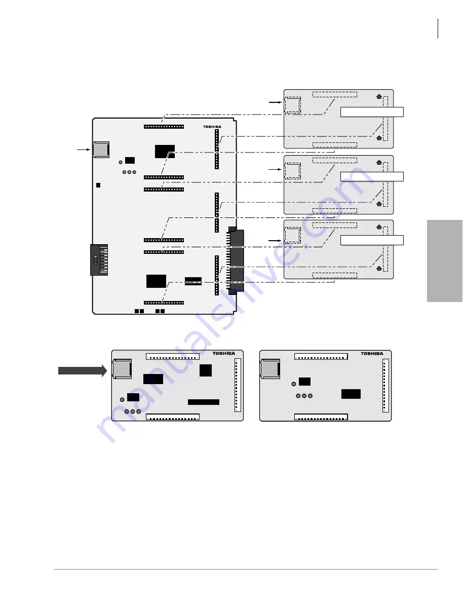
Figure 9-25 RSIU, RSIS, RMDS PCB Installation
R S I S 1 A
J4
J3
J1
1
17
1
17
11
7
J2
J4
J3
J1
1
17
1
17
11
7
J2
R M D S 1 A
CAUTION:
Do not connect
telephone circuit
Tip/Ring to J4
(See Note 2)
RMDS Top View
RSIS Top View
R S I U 1 A
V . 1
RSIU1
J4
J1
P2
P4
P5
P8
P11
P3
P7
P9
J3
J2
1
17
1
17
11
7
J1
UP
UP
J4
J3
J2
1
17
1
17
11
7
J1
UP
UP
J4
J3
J2
1
17
1
17
11
7
J1
UP
UP
Bottom View (solder side)
Port #4
3-Pair
Modular
Jack
Port #3
3-Pair
Modular
Jack
Port #2
3-Pair
Modular
Jack
Port #1
3-Pair
Modular
Jack
Each position on the RSIU card can
accept either an RSIS or RMDS (Note 1)
card. Only one RMDS card can be used
per RSIU. (See Note 1)
RSIS or RMDS
(Note 1)
RSIS or RMDS
(Note 1)
RSIS or RMDS
(Note 1)
1814
Notes
1. Maximum of one RMDS per RSIU, maximum of three RSIS per RSIU.
2. On RMDS, is not used for modem, operation. It is used when RMDS is configured for TTY, SMDI, or
MIS operation like RSIS.
Summary of Contents for Strata AirLink DK40i
Page 22: ...Introduction Related Documents Media xx Strata DK I M 6 00 ...
Page 48: ...DK14 Installation DK14 Wiring Diagrams 1 26 Strata DK I M 6 00 ...
Page 220: ...DK424 Installation Remote Cabinet Installation Instructions 5 68 Strata DK I M 6 00 ...
Page 262: ...DK424i Configuration Primary Reserve Power Cabinet Hardware 6 42 Strata DK I M 6 00 ...
Page 450: ...Universal Slot PCB Wiring Option Interface PCB Wiring Diagrams 10 42 Strata DK I M 6 00 ...
Page 592: ...Peripheral Installation Enhanced 911 Service E911 12 84 Strata DK I M 6 00 ...
Page 616: ...ACD Installation Spectrum Electronic Wall Boards 13 24 Strata DK I M 6 00 ...
Page 634: ...Fault Finding Fault Isolation Flowcharts 14 18 Strata DK I M 6 00 ...
Page 704: ...ISDN Interfaces ISDN Disconnect Cause Code 16 54 Strata DK I M 6 00 ...


