Universal Slot PCB Wiring
Cable Lengths
10-4
Strata DK I&M 6/00
Station Wiring Diagrams
Digital Station Wiring
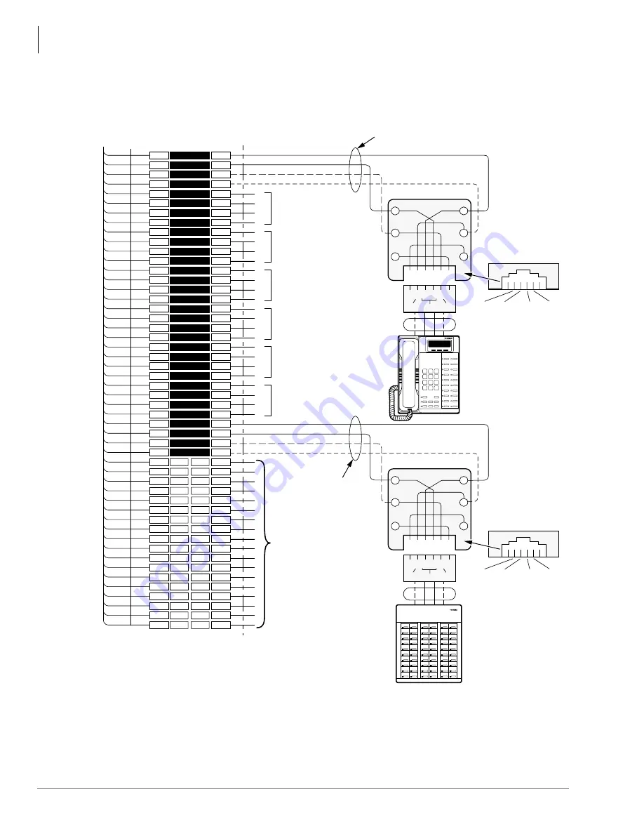
Figure 10-2
MDF Wiring for Digital Telephones (DKTs) and DDSS Console to PDKU
1
2
3
4
5
6
7
8
9
10
11
12
13
14
15
16
17
18
19
20
21
22
23
24
25
26
27
28
29
30
31
32
33
34
35
36
37
38
39
40
41
42
43
44
45
46
47
48
49
50
1
2
3
4
5
6
7
8
9
10
11
12
13
14
15
16
17
18
19
20
21
22
23
24
25
26
27
28
29
30
31
32
33
34
35
36
37
38
39
40
41
42
43
44
45
46
47
48
49
50
W-BL
BL-W
W-O
O-W
W-GN
GN-W
W-BR
BR-W
W-S
S-W
R-BL
BL-R
R-O
O-R
R-GN
GN-R
R-BR
BR-R
R-S
S-R
BK-BL
BL-BK
BK-O
O-BK
BK-GN
GN-BK
BK-BR
BR-BK
BK-S
S-BK
Y-BL
BL-Y
Y-O
O-Y
Y-GN
GN-Y
Y-BR
BR-Y
Y-S
S-Y
V-BL
BL-V
V-O
O-V
V-GN
GN-V
V-BR
BR-V
V-S
S-V
26
1
27
2
28
3
29
4
30
5
31
6
32
7
33
8
34
9
35
10
36
11
37
12
38
13
39
14
40
15
41
16
42
17
43
18
44
19
45
20
46
21
47
22
48
23
49
24
50
25
Bridging
Clips
To PDKU
W/Female Connector
25-Pair Cable W/Male Amp Connector
66M150 Split Block
Circuit 2 to DKT 2
or PDIU-DS
Circuit 3 to DKT 3
or PDIU-DS
Circuit 4 to DKT 4
or PDIU-DS
Circuit 6 to DKT 6
or PDIU-DS
Circuit 7 to DKT 7
or PDIU-DS
Circuit 5 to DKT 5
or PDIU-DS
or DDCB
(-) T1 (Voice/Data)
(GND) R1 (Voice/Data)
(-) PT1 (Add. Power)
(GND) PR1 (Add. Power)
T2
R2
PT2
PR2
T3
R3
PT3
PR3
T4
R4
PT4
PR4
T5
R5
PT5
PR5
T6
R6
PT6
PR6
T7
R7
PT7
PR7
(-) T8 (Voice/Data)
(GND) R8 (Voice/Data)
(-) PT (Add. Power)
(GND) PR (Add. Power)
Not Used
GN
6 5 4 3 2 1
Y
BL
R
BK
W
3 4
R8
PT8
T8
PR8
2
5
PR TR PT
Jacketed Twisted Pairs
24 AWG (1 or 2 pair. See Note 1.)
Station Cabling
GN
6 5 4 3 2 1
Y
BL
R
BK
W
3 4
R1
PT1
T1
PR1
2
5
PR TR PT
RJ11
RJ11
Digital Telephone
(With or Without PDIU-DI)
DDSS Console
(Circuit 8 Only)
or...
Digital
Telephone (DKT 8)
or...
PDIU-DS (with PDKU2)
(See Note 1)
Modular
Cord
Modular
Cord
GND
PR
(-)
T
GND
R
(-)
PT
GND
PR
(-)
T
GND
R
(-)
PT
1593
Notes
1. T/R wires are always required; PT/PR are additional power wires required
only for long station runs per
. PT/PR may be used with normal
station runs also.
2. Voltage levels:
T, PT = -26.3~27.8 VDC
R, PR = 0.0 VDC (GND). Reference to SG ground.
Summary of Contents for Strata AirLink DK40i
Page 22: ...Introduction Related Documents Media xx Strata DK I M 6 00 ...
Page 48: ...DK14 Installation DK14 Wiring Diagrams 1 26 Strata DK I M 6 00 ...
Page 220: ...DK424 Installation Remote Cabinet Installation Instructions 5 68 Strata DK I M 6 00 ...
Page 262: ...DK424i Configuration Primary Reserve Power Cabinet Hardware 6 42 Strata DK I M 6 00 ...
Page 450: ...Universal Slot PCB Wiring Option Interface PCB Wiring Diagrams 10 42 Strata DK I M 6 00 ...
Page 592: ...Peripheral Installation Enhanced 911 Service E911 12 84 Strata DK I M 6 00 ...
Page 616: ...ACD Installation Spectrum Electronic Wall Boards 13 24 Strata DK I M 6 00 ...
Page 634: ...Fault Finding Fault Isolation Flowcharts 14 18 Strata DK I M 6 00 ...
Page 704: ...ISDN Interfaces ISDN Disconnect Cause Code 16 54 Strata DK I M 6 00 ...


