Station Apparatus
Telephone Installation
Strata DK I&M 6/00
11-3
Station Apparatus
Telephone Installation
This
section
describes the wiring required to connect telephones to the system. Before installing
any telephone wiring, read the following warning and caution notes:
CAUTION!
When installing the station cable, do not run the cables parallel if they are
within three feet of an AC power line. AC power lines should be crossed at right
(90
°
) angles only. In particular, avoid running station wire pairs near devices
that generate electrical noise, such as neon or fluorescent light fixtures.
Important!
For station apparatus secondary protection information, refer to the following:
DK14, see
; DK40i, see
;
DK424, see
; or for DK424i, see
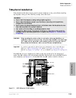
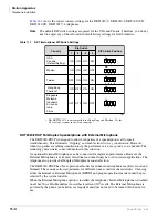
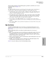
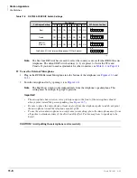
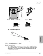
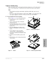
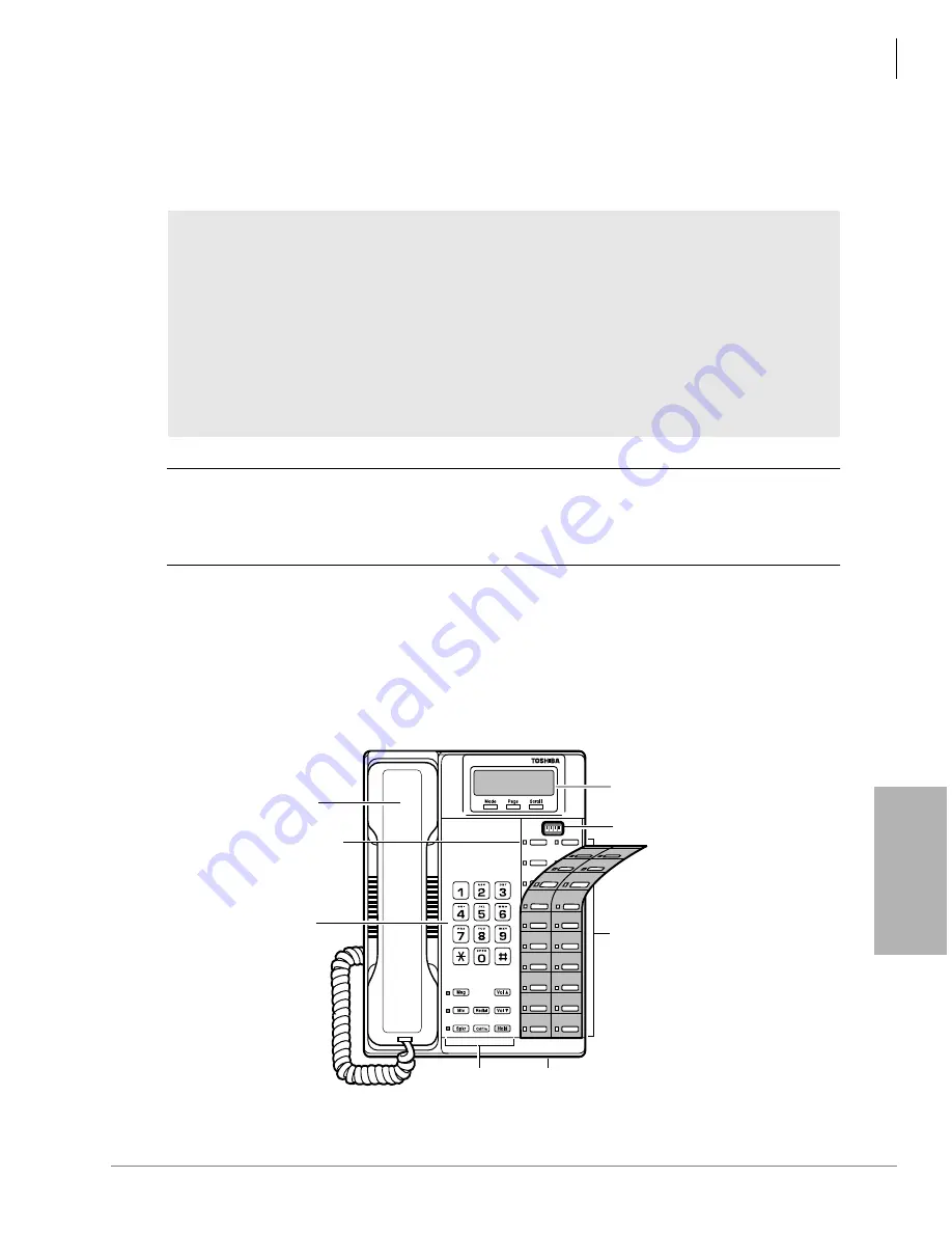
The DKT2000 V.4 series telephones have DIP switches that enable use for the international
market. The DIP switches are located underneath the flexible button key strip on the DKT2000 V.4
series telephones (see
). On the DKT2001, the DIP switch is located on the base.
S
Figure 11-1
DKT 2000-series V.4 DIP Switches
WARNING!
➤
Never install the telephone wiring during a lightning storm.
➤
Never install the telephone jacks in wet locations, unless the jack is specifically
designed for wet locations.
➤
Never touch uninsulated telephone wires or terminals unless the telephone line has
been disconnected at the network interface.
➤
Use caution when installing or modifying telephone lines.
➤
If telephone, DSS console, door phone control box, or door phone wiring exits the
building, external secondary protection is required. See
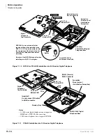
Line 9
Line 8
Line 7
Line 6
Line 5
Line 4
Line 3
Line 2
Line 1
Intercom
Speed
Dial
Do Not
Disturb
Line 17
Line 16
Line 15
Line 14
Line 13
Line 12
Line 11
Line 10
ON
1
2
3
4
Fixed Buttons
Microphone Location
Dial Pad
Handset
Red/Green
LED Indicators
DIP Switches
(some models)
3926
LCD Display
Flexible Buttons
Summary of Contents for Strata AirLink DK40i
Page 22: ...Introduction Related Documents Media xx Strata DK I M 6 00 ...
Page 48: ...DK14 Installation DK14 Wiring Diagrams 1 26 Strata DK I M 6 00 ...
Page 220: ...DK424 Installation Remote Cabinet Installation Instructions 5 68 Strata DK I M 6 00 ...
Page 262: ...DK424i Configuration Primary Reserve Power Cabinet Hardware 6 42 Strata DK I M 6 00 ...
Page 450: ...Universal Slot PCB Wiring Option Interface PCB Wiring Diagrams 10 42 Strata DK I M 6 00 ...
Page 592: ...Peripheral Installation Enhanced 911 Service E911 12 84 Strata DK I M 6 00 ...
Page 616: ...ACD Installation Spectrum Electronic Wall Boards 13 24 Strata DK I M 6 00 ...
Page 634: ...Fault Finding Fault Isolation Flowcharts 14 18 Strata DK I M 6 00 ...
Page 704: ...ISDN Interfaces ISDN Disconnect Cause Code 16 54 Strata DK I M 6 00 ...


