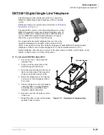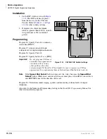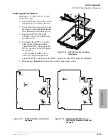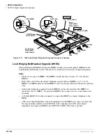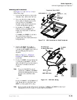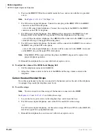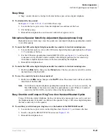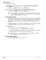
Station Apparatus
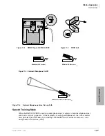
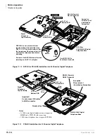
Dip Switches
11-10
Strata DK I&M 6/00
Digital telephones that are equipped with Integrated Data Interface Units or ADMs should have
two-pair (or external power) to function effectively at this distance. This also applies to digital
telephones supported by systems that must operate with battery reserve power (see Chapter 5 –
DK424 Installation,
To accommodate the digital telephone line cord, the cable should be terminated in a modular
station connector block (RJ11) at the station location. The standard single-pair, modular digital
telephone cord that is sent with the telephone is 7 ft. (the maximum allowed is 25 ft.).
Note
Digital telephone cable runs must not have cable splits (single or double), cable bridges
(of any length), or high resistance or faulty cable splices.
Electronic Telephones
The following provides information on how to connect electronic telephones to the Strata DK
system.
Note
Before proceeding, see warning and caution notes in
“Telephone Installation” on Page
Electronic telephones are connected to electronic telephone circuits in the DK40i Expansion Unit
on the Electronic Telephone Interface Unit (PEKU) and the Standard/Electronic Telephone
Interface Unit (PESU) via the MDF with standard twisted-pair jacketed telephone cable. Two-pair
wiring, as a minimum, is required for telephone connection. However, three-pair wiring is
recommended for some upgrades, such as OCA.
To accommodate the electronic telephone line cord, the cable should be terminated in a modular
station connector block (RJ11) at the station location. The standard two-pair modular electronic
telephone cord length is 7 feet (the maximum allowed length is 25 feet). See
for more details.
If using 24 AWG cable, the overall length of the station cable run from the DK40i Base KSU to the
telephone must not exceed 1,000 feet (305 meters).
Standard Telephones
The following provides information on how to connect standard telephones to the DK system.
Note
Before proceeding, see warning and caution notes in
“Telephone Installation” on Page
Standard telephones connect to standard telephone circuits of the Standard Telephone Interface
PCBs: RSTU, RSTU2, RDSU/RSTS, PSTU, PESU, KSTU2 (DK40i only), and QSTU2 (DK14
only). Standard telephones connect to RSTU, RDSU/RSTS, PSTU or PESU via the MDF with
standard twisted-pair jacketed telephone cable. (See single-pair wiring
for more details.)
The standard telephone cable’s overall loop resistance, connected on- or off-premises, is 300 ohms
maximum, (for PSTU, PESU, KSTU2, or QSTU2), 600 ohms for RSTU and RDSU/RSTS with
-24VDC (
no
R48S), and 1200 ohms for RSTU and RDSU/RSTS with -48VDC (R48S installed on
RSTU, RSTU2, or RDSU PCB), including the telephone resistance. This also applies to all devices
connected to standard telephone circuits.
A standard telephone connected off-premises via the telephone network should interface with
OL13A, OL13B, or OL13C lines (or equivalent) and connect to an RJ21X, FIC jack or equivalent,
(see wiring diagrams in
Summary of Contents for Strata AirLink DK40i
Page 22: ...Introduction Related Documents Media xx Strata DK I M 6 00 ...
Page 48: ...DK14 Installation DK14 Wiring Diagrams 1 26 Strata DK I M 6 00 ...
Page 220: ...DK424 Installation Remote Cabinet Installation Instructions 5 68 Strata DK I M 6 00 ...
Page 262: ...DK424i Configuration Primary Reserve Power Cabinet Hardware 6 42 Strata DK I M 6 00 ...
Page 450: ...Universal Slot PCB Wiring Option Interface PCB Wiring Diagrams 10 42 Strata DK I M 6 00 ...
Page 592: ...Peripheral Installation Enhanced 911 Service E911 12 84 Strata DK I M 6 00 ...
Page 616: ...ACD Installation Spectrum Electronic Wall Boards 13 24 Strata DK I M 6 00 ...
Page 634: ...Fault Finding Fault Isolation Flowcharts 14 18 Strata DK I M 6 00 ...
Page 704: ...ISDN Interfaces ISDN Disconnect Cause Code 16 54 Strata DK I M 6 00 ...


