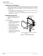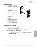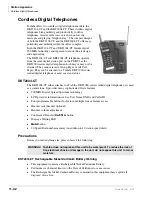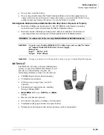
Station Apparatus
Electronic Telephone Upgrades
11-24
Strata DK I&M 6/00
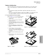
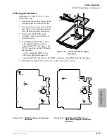
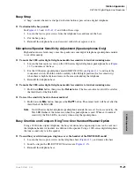
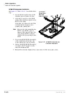
HVSU/HVSI Upgrade Installation
and follow these
steps:
1. Loosen the four captive screws on the
telephone base and remove the base.
2. Align the P5 connector on the HVSI
subassembly with the receptacle on the
HVSU subassembly.
Apply firm, even pressure to the PCBs
to ensure that the connectors mate
properly (they should click).
Note
Exercise care when assembling the
HVSU to the HVSI to prevent
damage to the connector pins; also,
verify that the HVSU is aligned
with the silk-screened image on the
HVSI.
3. Position the HVSU/HVSI subassembly
on the standoffs inside the base, and
secure with the two screws provided.
4. Connect the HVSU/HVSI subassembly
wire plug to the P2 connector on the
electronic telephone PCB.
5. Reinstall the electronic telephone base, and secure it with its four captive screws.
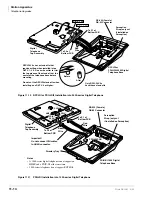
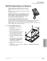
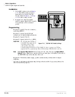
To P2 HVSU
Connector on
Main PCB
Inside Telephone
HSVI
P5
HVSU
1491
Figure 11-21
HVSI/HVSU Installation for
Electronic Telephones
Summary of Contents for Strata AirLink DK40i
Page 22: ...Introduction Related Documents Media xx Strata DK I M 6 00 ...
Page 48: ...DK14 Installation DK14 Wiring Diagrams 1 26 Strata DK I M 6 00 ...
Page 220: ...DK424 Installation Remote Cabinet Installation Instructions 5 68 Strata DK I M 6 00 ...
Page 262: ...DK424i Configuration Primary Reserve Power Cabinet Hardware 6 42 Strata DK I M 6 00 ...
Page 450: ...Universal Slot PCB Wiring Option Interface PCB Wiring Diagrams 10 42 Strata DK I M 6 00 ...
Page 592: ...Peripheral Installation Enhanced 911 Service E911 12 84 Strata DK I M 6 00 ...
Page 616: ...ACD Installation Spectrum Electronic Wall Boards 13 24 Strata DK I M 6 00 ...
Page 634: ...Fault Finding Fault Isolation Flowcharts 14 18 Strata DK I M 6 00 ...
Page 704: ...ISDN Interfaces ISDN Disconnect Cause Code 16 54 Strata DK I M 6 00 ...

