Station Apparatus
Cordless Digital Telephones
11-34
Strata DK I&M 6/00
Cordless Telephone Installation (DKT2004-CT and DKT2104-CT)
Important!
Your telephone system must be programmed for Auto Preference for your TALK
button to work. If there is a shared digital telephone, you receive internal system
dial tone automatically after picking up the handset of your deskset. For example, in
a DK system, Program 32 must have a setting other than “00.” It is best to set Auto
Line Preference to access Intercom dial tone.
➤
To install the cordless telephone
1. Select a location for your cordless digital telephone. Avoid excessive heat or humidity. For
wall mounting, refer to the following section.
2. Place the cordless digital telephone’s base unit on a desk or tabletop near a standard 120VAC
outlet and within reach of the digital telephone line connection to your Strata DK system.
3. Keep the base unit and handset away from sources of electrical noise (motors, fluorescent
lighting, etc.).
Important!
Place the cordless telephone to the right of the DKT. If placed on the left of the DKT,
the cordless antenna will pick up a tone due to its close proximity to the DKT
speaker and electronic parts.
➤
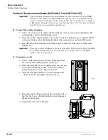
To mount on a wall
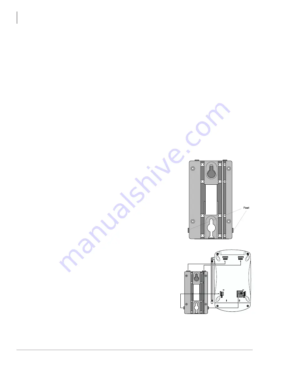
1. Select a wall location near a 120VAC outlet and within
reach of the Strata DK digital line connection.
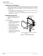
2. Place the wall plate (shown at right) against the wall, and
with a pencil, mark the position of the screws.With a
punch tool, punch “starter” holes in the wall.
3. Align the wall plate and screws on the wall where the
“starter” holes are and tighten down the screws.
4. Ensure that the wall-mount plate is placed on the wall so
that the “feet” are at the bottom when you are looking at
the inside of the plate.
5. Snap the Base Unit onto the plate.
4449
4507
Summary of Contents for Strata AirLink DK40i
Page 22: ...Introduction Related Documents Media xx Strata DK I M 6 00 ...
Page 48: ...DK14 Installation DK14 Wiring Diagrams 1 26 Strata DK I M 6 00 ...
Page 220: ...DK424 Installation Remote Cabinet Installation Instructions 5 68 Strata DK I M 6 00 ...
Page 262: ...DK424i Configuration Primary Reserve Power Cabinet Hardware 6 42 Strata DK I M 6 00 ...
Page 450: ...Universal Slot PCB Wiring Option Interface PCB Wiring Diagrams 10 42 Strata DK I M 6 00 ...
Page 592: ...Peripheral Installation Enhanced 911 Service E911 12 84 Strata DK I M 6 00 ...
Page 616: ...ACD Installation Spectrum Electronic Wall Boards 13 24 Strata DK I M 6 00 ...
Page 634: ...Fault Finding Fault Isolation Flowcharts 14 18 Strata DK I M 6 00 ...
Page 704: ...ISDN Interfaces ISDN Disconnect Cause Code 16 54 Strata DK I M 6 00 ...

