Peripheral Installation
Relay Control Options and Door Lock Control
Strata DK I&M 6/00
12-11
Pe
ri
p
h
er
a
l In
st
al
la
ti
on
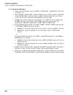
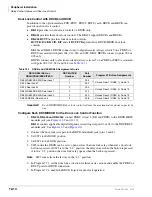
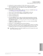
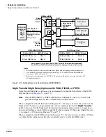
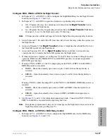
Configure PIOU, PIOUS or PEPU for External Page Mute Option
1. Set Program 77-1 LED 07 to Off to configure the PIOU, PIOUS, or PEPU PCB for the
external page function.
2. If using a PIOU or PEPU, set the jumper plug P10 on the PIOU or PEPU jumper plug to the
MAKE or BREAK position as required:
♦
MAKE – Shorts the normally open contacts (pins 7 and 32) when external page is
activated.
♦
BREAK – Opens the normally closed contacts (pins 7 and 32) when external page is
activated.
...or
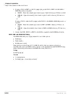
If using a PIOUS, solder the jumper W1 on the PIOUS to the MAKE or BREAK position as
required:
♦
MAKE – Shorts the normally open contacts (DET and DER) when external page is
activated.
♦
BREAK – Opens the normally closed contacts (DET and DER) when external page is
activated.
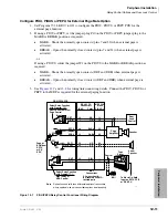
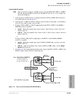
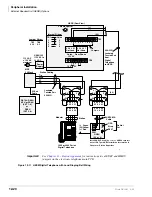
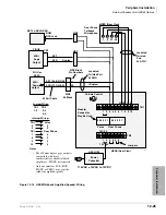
3. See
for wiring/interconnecting details. Connect the PIOU, PIOUS, or
PEPU to the MDF as required for the external paging function.
Figure 12-7
PIOU/PEPU Relay Control Functional Wiring Diagram
PIOU 25 PR.
Connectors
PIN NO.
Color
MDF 66M
Block
PIN NO.s
PIOU/PEPU PCB
Door
Lock
Control
8 ohm
Speaker
Page
Amplifier
Select Relay Function
with Program 77-1
Door Lock or External
Page Control
Break
P10
Make
SW4
SP0
SP1
VR1
600
Ω
(Duplex)
8
Ω
3 Watt
P11
Break
Make
Night
Bell
To Music On-Hold
Input on RCTU PCB
or DK KSU
MDF
Connections
All wires should
be jacketed 24 AWG
twisted pairs
Select Relay Function
with Program 77-1:
Night Relay or
MOH Control
32
7
38
13
50
25
34
9
R-O
O-R
Bk-Gn
Gn-Bk
V-S
S-V
R-Br
Br-R
13
14
25
26
49
50
17
18
.
.
.
.
.
.
.
.
DE.T
DE. R
SP.T0
SP.R0
SP.T1
SP.R1
NH.T
NH.R
Control
Speaker
Tape
Player
Page or
BGM from
RCTU
or DK
KSU
1507
Note
Dotted lines and solid lines differentiate optional connections
where applicable; do not connect both options simultaneously.
Summary of Contents for Strata AirLink DK40i
Page 22: ...Introduction Related Documents Media xx Strata DK I M 6 00 ...
Page 48: ...DK14 Installation DK14 Wiring Diagrams 1 26 Strata DK I M 6 00 ...
Page 220: ...DK424 Installation Remote Cabinet Installation Instructions 5 68 Strata DK I M 6 00 ...
Page 262: ...DK424i Configuration Primary Reserve Power Cabinet Hardware 6 42 Strata DK I M 6 00 ...
Page 450: ...Universal Slot PCB Wiring Option Interface PCB Wiring Diagrams 10 42 Strata DK I M 6 00 ...
Page 592: ...Peripheral Installation Enhanced 911 Service E911 12 84 Strata DK I M 6 00 ...
Page 616: ...ACD Installation Spectrum Electronic Wall Boards 13 24 Strata DK I M 6 00 ...
Page 634: ...Fault Finding Fault Isolation Flowcharts 14 18 Strata DK I M 6 00 ...
Page 704: ...ISDN Interfaces ISDN Disconnect Cause Code 16 54 Strata DK I M 6 00 ...

