Peripheral Installation
External Speaker Unit (HESB) Options
Strata DK I&M 6/00
12-19
Pe
ri
p
h
er
a
l In
st
al
la
ti
on
External Speaker Unit (HESB) Options
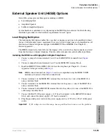
Strata DK systems provide three options utilizing an HESB:
♦
Loud Ringing Bell
♦
Amplified Speaker
♦
Talkback Amplified Speaker
System hardware requirements vary depending on the HESB option selected. See the following
installation procedures for the hardware requirements for each option.
Loud Ringing Bell Option
The loud ringing bell option enables the voice first or ringing signal tone to be amplified without
the use of other manufacturers’ equipment. The voice first and signal tone can be amplified on all
electronic and digital telephones equipped with HHEU PCBs and HESB. (See Chapter 11 –
Station Apparatus.)
The HESB automatically turns Off once the ringing call or voice first has been manually answered
from the electronic or digital telephone. This turn-off feature prevents audio feedback problems.
Installing the HESB Loud Ringing Bell in Digital Telephones
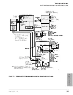
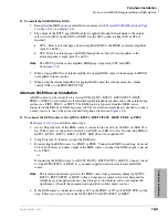
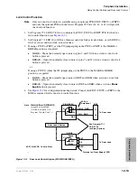
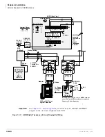
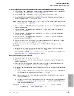
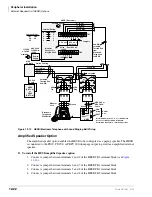
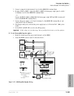
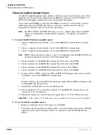
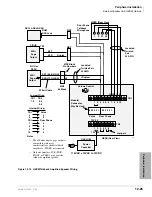
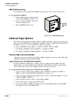
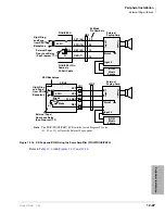
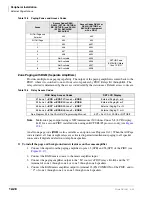
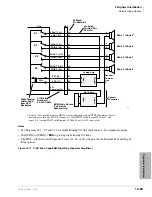
1. Connect a jumper between terminals 2 and 10 on the HESB TB1 terminal block (
2. Connect a jumper between terminals 4 and 5 on the HESB TB2 terminal block.
3. Install an HHEU PCB and HESC-65A cable in the telephone per Chapter 11 – Station
Apparatus before proceeding with
.
Note
HESB connections made in
can be accomplished using the HESB VOICE
modular jack instead of the TB1 terminal block.
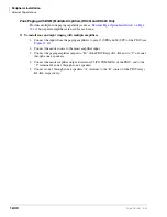
4. Connect terminal 1 of the HESB TB1 terminal block to the red (+) wire of the HESC-65A
using a modular block.
5. Connect terminal 2 of the HESB TB1 terminal block to the green (-) wire of the HESC-65A
using a modular block.
6. Connect terminal 8 of the HESB TB1 terminal block to the yellow (L2) wire of the HESC-65A
cable using a modular block.
7. Connect the HACU-120 power supply’s +12V lead to terminal 1 of the HESB TB2 terminal
block, and connect the power supply’s 0V lead to terminal 2.
8. Plug the provided power cord into the power supply and to a 115VAC ± 10VAC, 60Hz power
source.
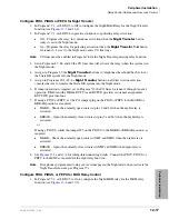
Important!
If AC voltage is not within range, have a qualified electrician correct the problem.
Summary of Contents for Strata AirLink DK40i
Page 22: ...Introduction Related Documents Media xx Strata DK I M 6 00 ...
Page 48: ...DK14 Installation DK14 Wiring Diagrams 1 26 Strata DK I M 6 00 ...
Page 220: ...DK424 Installation Remote Cabinet Installation Instructions 5 68 Strata DK I M 6 00 ...
Page 262: ...DK424i Configuration Primary Reserve Power Cabinet Hardware 6 42 Strata DK I M 6 00 ...
Page 450: ...Universal Slot PCB Wiring Option Interface PCB Wiring Diagrams 10 42 Strata DK I M 6 00 ...
Page 592: ...Peripheral Installation Enhanced 911 Service E911 12 84 Strata DK I M 6 00 ...
Page 616: ...ACD Installation Spectrum Electronic Wall Boards 13 24 Strata DK I M 6 00 ...
Page 634: ...Fault Finding Fault Isolation Flowcharts 14 18 Strata DK I M 6 00 ...
Page 704: ...ISDN Interfaces ISDN Disconnect Cause Code 16 54 Strata DK I M 6 00 ...

