Peripheral Installation
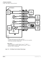
External Speaker Unit (HESB) Options
Strata DK I&M 6/00
12-21
Pe
ri
p
h
er
a
l In
st
al
la
ti
on
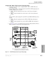
Installing the HESB Loud Ringing Bell in Electronic Telephones (DK40i and DK424 Only)
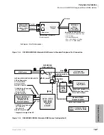
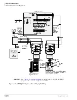
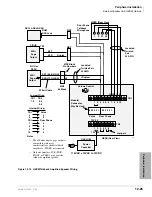
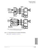
1. On the HESB TB1 terminal block: connect a jumper between terminals 6 and 7, and connect
another jumper between terminals 5 and 8 (see
2. On the HESB TB2 terminal block, connect a jumper between terminals 4 and 5.
3. Install an HHEU PCB and HESC-65A (or HESC-65A) cable in the telephone per Chapter 11 –
Station Apparatus before proceeding with
Note
HESB connections made in
can be made with the HESB VOICE modular jack
instead of the TB1 terminal block.
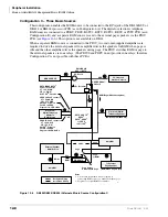
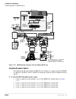
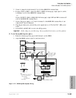
4. Connect terminal 1 of the HESB TB1 terminal block to the red (+) wire of the HESC-65 cable
using a modular block.
5. Connect terminal 2 of the HESB TB1 terminal block to the green (-) wire of the HESC-65
cable using a modular block.
6. Connect terminal 3 of the HESB TB1 terminal block to pin 3 of the electronic telephone’s
modular block (VOICE TIP).
7. Connect terminal 4 of the HESB TB1 terminal block to pin 4 of the electronic telephone’s
modular block (VOICE RING).
8. Connect the HACU-120 power supply’s +12V lead to terminal 1 of the HESB TB2 terminal
block, and connect the power supply’s 0V lead to terminal 2.
9. Plug power cord into the power supply and to a 115VAC±10VAC, 60Hz power source.
Important!
●
Make sure the AC power is within the specified limits shown in Step 9. If AC voltage is not
within range, have a qualified electrician correct the problem.
●
Cut the EX-SP and HHEU straps on telephones and do not cut the OCA strap or R607 on the
HHEU (see
Chapter 11 – Station Apparatus
for details).
Testing the Loud Ringing Bell Option
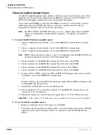
1. Test the AC input voltage. See Step 9, above.
2. Make a CO or station call to the station configured for the loud ringing bell. Ringing will be
heard over the HESB.
3. Use a small, slotted screwdriver to turn the volume control on the back of the HESB to the
desired level and adjust the ring volume control on the telephone.
4. If ringing is heard at the station, but not over the HESB, check the following while the station
is ringing:
♦
Using a suitable voltmeter, measure voltage across terminals 1 (+) and 2 (-) of the HESB
TB1 terminal block. Voltage indication should be 4.5~5VDC.
Note
Ringing stops once the call is manually answered. There should be NO voltage potential
across terminals 1 and 2.
♦
If voltage is not as specified during ringing, check that the telephone wiring connections to
the HESB have been made properly (wires to terminals 1 and 2 of the HESB TB1 terminal
block may have been reversed).
Important!
See
Chapter 11 – Station Apparatus
for instructions to cut EXSP and HHEU
jumpers on the electronic telephone main PCB.
Summary of Contents for Strata AirLink DK40i
Page 22: ...Introduction Related Documents Media xx Strata DK I M 6 00 ...
Page 48: ...DK14 Installation DK14 Wiring Diagrams 1 26 Strata DK I M 6 00 ...
Page 220: ...DK424 Installation Remote Cabinet Installation Instructions 5 68 Strata DK I M 6 00 ...
Page 262: ...DK424i Configuration Primary Reserve Power Cabinet Hardware 6 42 Strata DK I M 6 00 ...
Page 450: ...Universal Slot PCB Wiring Option Interface PCB Wiring Diagrams 10 42 Strata DK I M 6 00 ...
Page 592: ...Peripheral Installation Enhanced 911 Service E911 12 84 Strata DK I M 6 00 ...
Page 616: ...ACD Installation Spectrum Electronic Wall Boards 13 24 Strata DK I M 6 00 ...
Page 634: ...Fault Finding Fault Isolation Flowcharts 14 18 Strata DK I M 6 00 ...
Page 704: ...ISDN Interfaces ISDN Disconnect Cause Code 16 54 Strata DK I M 6 00 ...

