Peripheral Installation
Two-CO Line External Amplified Conference
Strata DK I&M 6/00
12-33
Pe
ri
p
h
er
a
l In
st
al
la
ti
on
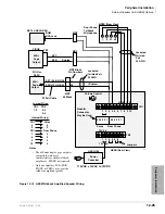
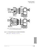
Amplified Talk Path
provides a functional diagram of a two-CO line amplified conference connection. (A
tellabs 7206 amplifier is used here.) The talk path for the connection is as follows: outside party 1
– public telephone network – CO PCB, CKTX – RCTU or BCU – PEKU, port A – into AMP, Line
in, – AMP, Line out – PEKU, port B – RCTU or BCU – CO PCB, CKTY – public telephone
network – outside party 2. This path is two-way so when outside party 2 talks, the talk level is
amplified in the reverse direction.
Note
Only the outside party 1 talk path is amplified to/from a system telephone when it is
connected into a two-CO line conference.
Amplifier Requirements
♦
Customer-supplied amplifier (two maximum for DK40i and four maximum for DK424 and
DK424i).
♦
Must be FCC-registered, Part 68, and must provide automatic gain control.
♦
Each amplifier requires two PEKU station ports.
♦
See the amplifier manufacturer’s installation documentation for amplifier grounding
instructions.
➤
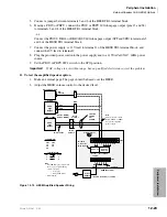
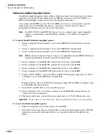
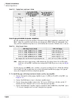
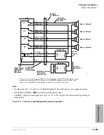
To connect a two-way amplifier to the Strata DK system
1. At the MDF, connect the voice pair (VT, VR, port A) of circuit 2 on the designated PEKU
PCB to one input of the customer-supplied two-way amplifier. In the example in
this is CKTA (CO Side A) of the amplifier. (See the Amplified Two-CO Line Conference
wiring diagram in
Chapter 10 – Universal Slot PCB Wiring
2. At the MDF, connect the voice pair (VT, VR, port B) of circuit 3 on the designated PEKU PCB
to the other input of the amplifier. In
, this is CKTB (subscriber side B) of the
amplifier.
3. Plug the amplifier’s power cord into the 117VAC (standard) wall outlet.
4. Set the gain and other amplifier options per the manufacturer’s installation documentation.
Amplifier Programming
♦
Program 10-1: LEDs 19 and 20 must be On.
♦
Program 10-2: LED 18 must be On.
♦
Program 10-3: Enables the appropriate PEKU PCB ports for amplifier connection. Only
enable the ports that will be connected with the amplifier(s).
♦
Program 15-5: Enables appropriate CO lines for Two-CO line tandem connection.
Note
LED 19 in Program 10-1 should be On if it is certain that an amplifier will always be
available for two-CO line conference connections (four maximum, simultaneously). If this
LED is On and a two-CO line connection is established without an external amplifier, the
Strata DK424 station may be unbalanced and may receive a hum noise. LED 19 provides
additional station amplification when external amplifiers are switched into two-CO line
connections.
♦
Program 78-2: Enables appropriate CO lines if amplified DISA is required.
Summary of Contents for Strata AirLink DK40i
Page 22: ...Introduction Related Documents Media xx Strata DK I M 6 00 ...
Page 48: ...DK14 Installation DK14 Wiring Diagrams 1 26 Strata DK I M 6 00 ...
Page 220: ...DK424 Installation Remote Cabinet Installation Instructions 5 68 Strata DK I M 6 00 ...
Page 262: ...DK424i Configuration Primary Reserve Power Cabinet Hardware 6 42 Strata DK I M 6 00 ...
Page 450: ...Universal Slot PCB Wiring Option Interface PCB Wiring Diagrams 10 42 Strata DK I M 6 00 ...
Page 592: ...Peripheral Installation Enhanced 911 Service E911 12 84 Strata DK I M 6 00 ...
Page 616: ...ACD Installation Spectrum Electronic Wall Boards 13 24 Strata DK I M 6 00 ...
Page 634: ...Fault Finding Fault Isolation Flowcharts 14 18 Strata DK I M 6 00 ...
Page 704: ...ISDN Interfaces ISDN Disconnect Cause Code 16 54 Strata DK I M 6 00 ...

