Peripheral Installation
SMDR Printer/Call Accounting Device Options
12-36
Strata DK I&M 6/00
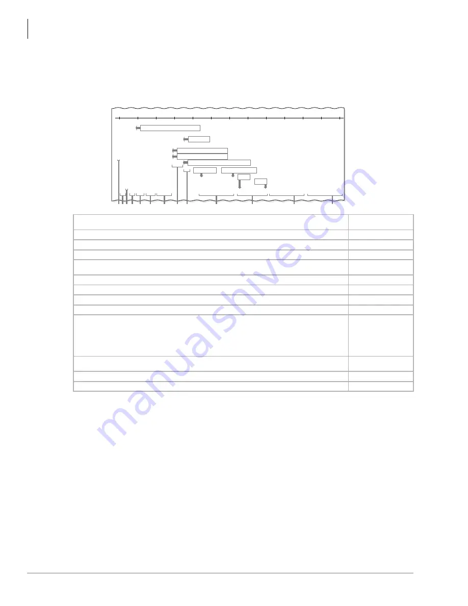
shows a sample SMDR printout and describes the contents of each
column. The following examples show call record samples and describe the sequence of events
that generated the call records.
If a subaddress for a call is received or sent on an ISDN call, it is included in the SMDR.
Subaddresses may/may not be received/sent on all ISDN calls.
1. Call Duration (incoming, outgoing, or transfer) must be 1 or 10 secs. (set by Program 60-2) to generate a call record printout.
2. “MSS”: designates a DISA or CF–External CO call to an unanswered station or answered after 1 or 10 secs. (threshold) per
Program 60-2. The call registers as a normal incoming call if answered before the threshold time. DISA calls always register
5~6 seconds ring before answer duration time.
3. Field column information is provided for SMDR output formatting purposes.
4. A “*” in the first column indicates a disconnected call by the CO Calling Party Control (CPC) or Automatic Release signal.
Loop start CO lines must have Programs 15-0 and 15-3 enabled before the CPC is dropped.
5. Answered calls ANI, DNIS, and Caller ID data transmits using the SMDR port. Abandoned calls data is not transmitted, but can
be stored in station memory. See Program *51 and *52.
6. See Program 60-1.
7. Strata DK sends a Carriage Return (CR) and Line Feed (LF) ASCII symbol after each line of data.
General Notes
The call record data is ASCII-formatted, 8 bits; no parity, 1-stop bit.
Special dial printout: Tone = “T”, Long pause = “L”, Flash = “F”, Pause = “P”
“DISA”: designates a DISA or CF–External call through the system via CO-to-CO connection.
“MODM”: designates a call to the IMDU, Remote Maintenance Modem.
Figure 12-20 SMDR Output
A
= Non-ISDN call established, then network disconnects. A = ISDN call established, then DK disconnects. + = ISDN
call established, then network disconnects. S = Start of E911 call. E = End of E911 call.
4
Field Number 1
B
CO Line Number (001~144).
Field Number (2~4)
3
C
C = Caller ID Call; D = ANI or DNIS Call.
Field Number 5
D
[PDN] of the Station (1~4 digits)
2
making/answering a call.
Field Number (7~10)
3
E
Primary, Secondary, or Phantom Directory Number which made/answered the call (1~4 digits). Blank if call is made
from a CO line button.
Field Number (12-15)
3
F
Time of Day (HH:MM:SS).
1
Field Number (17-21)
3
G
Call Duration (HH:MM:SS).
1
Field Number (23-30)
3
H
CO Line Incoming Ring Duration Before Answer (MM:SS).
Field Number (32-36)
3
I
Station to which the CO line was transferred (1~4 digits).
Field Number (38-41)
3
J
Telephone Number
●
Incoming (1~20 digits)
5
ANI (10 digits), DNIS (2~5 digits), Caller ID Number or ID Code
●
Outgoing Number (1~20 digits)
●
E911 Station ID (Prg *12)
Field Number (43-63)
3
ANI/DN
,6
Format:
7145833730
3846
Field Number (43~52)
K
DNIS NAME
5
(0~16 characters); Caller ID Name
5
(0~16 characters), or Account Code
6
(4~15 digits); LCD User
Name on E911 Calls
Field Number (65~80)
3
L
Outgoing Subaddress on ISDN call.
Field Number (82~101)
M
Incoming Subaddress on ISDN call.
Field Number (103~122)
1
001
001
003
003
001
003
003
003
004
003
002
*
D
C
205
MODM
200D
DISA
DISA
MSS
205
202
200
200
205
2 0 5
5 0 0
2 0 0
11/06/97
0 8 : 1 4
0 8 : 1 5
0 8 : 1 6
0 8 : 1 6
0 8 : 1 7
0 8 : 1 8
0 8 : 1 9
0 8 : 1 9
0 8 : 2 0
0 8 : 2 2
0 8 : 2 3
0 0 : 0 0 ; 2 2
0 0 : 0 0 ; 1 8
0 0 : 0 0 ; 2 8
0 0 : 0 0 ; 1 5
0 0 : 0 0 ; 2 5
0 0 : 0 0 ; 1 2
0 0 : 0 0 ; 2 2
0 0 : 0 0 ; 1 6
0 0 : 0 0 ; 3 4
0 0 : 0 0 ; 2 2
0 0 : 0 0 ; 4 0
1 2 3 4 5 6 9 8 7
1 2 3 4 5 6 7 8 9 0 1 2 3 4 5 6 7 8 9
7 1 4 5 9 3 3 7 0 0
7 1 4 5 8 3 3 7 0 0
4 5 6 7 8 9 7
1 2 3 4 5 6 7 8 9 4 5 6 3 2 1 0
1 9 9 3 0 2 1 9 7 7
0 9 3 7 7 2 9 8 1
00;00
00;08
00;06
sw
10
20
30
40
50
60
70
80
90
100
110
120
MM/DD/ YY, Every Fifty Call Records and at Midnight
DISA Call to IMDU
205 Answers DISA Call 12 Seconds After DK Dial Tone
Outgoing DISA Access by Incoming DISA 01
Incoming DISA and Access CO 03 Outgoing
First Digit (varies)
Last Digit (always this column)
First Digit
Last Digit
A B C D
E
F
G
H
I
J
K
L
M
2890
Summary of Contents for Strata AirLink DK40i
Page 22: ...Introduction Related Documents Media xx Strata DK I M 6 00 ...
Page 48: ...DK14 Installation DK14 Wiring Diagrams 1 26 Strata DK I M 6 00 ...
Page 220: ...DK424 Installation Remote Cabinet Installation Instructions 5 68 Strata DK I M 6 00 ...
Page 262: ...DK424i Configuration Primary Reserve Power Cabinet Hardware 6 42 Strata DK I M 6 00 ...
Page 450: ...Universal Slot PCB Wiring Option Interface PCB Wiring Diagrams 10 42 Strata DK I M 6 00 ...
Page 592: ...Peripheral Installation Enhanced 911 Service E911 12 84 Strata DK I M 6 00 ...
Page 616: ...ACD Installation Spectrum Electronic Wall Boards 13 24 Strata DK I M 6 00 ...
Page 634: ...Fault Finding Fault Isolation Flowcharts 14 18 Strata DK I M 6 00 ...
Page 704: ...ISDN Interfaces ISDN Disconnect Cause Code 16 54 Strata DK I M 6 00 ...

