Peripheral Installation
PC/Data Communications Interface Units
12-64
Strata DK I&M 6/00
Modem Setup Recommendations
1. Always make sure the escape sequence of the telephone PDIU-DI is default (+++).
2. Send AT command ATS2=43 to PDIU-DI.
3. Use a modified modem cable for the connection (see
and
) or reset the
PDIU-DS internal jumper plugs per the instructions in the
DK Admin User Guide
.
4. Send the following AT commands to the modem pool modem: ATS0=1, ATE0, ATQ0,
AT&C1, and AT&D2.
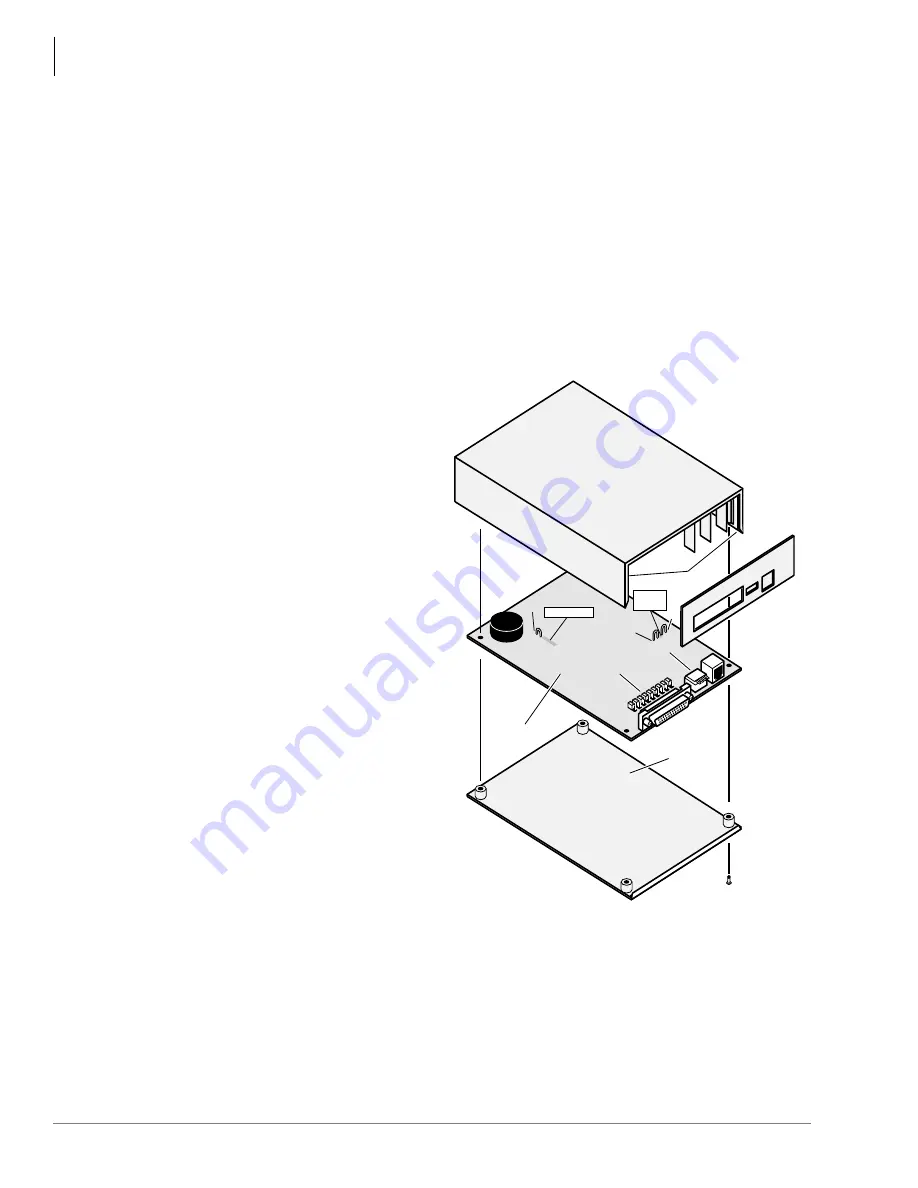
PDIU-DS Disassembly and Assembly
To set the jumper plugs (P1~P9) on the PCB inside the PDIU-DS for DCE or DTE operation, the
PDIU-DS must be disassembled.
➤
To disassemble the PDIU-DS
1. Remove the four non-captive
screws on the bottom of the unit
(
); these screws are
needed in Step 3 of the
assembling procedure.
2. Remove the bottom panel.
3. Remove the PCB inside the
PDIU-DS by lifting the back
panel from its side grooves.
4. Turn the PCB over and set the
jumper plugs (P1~P9):
♦
If the PDIU-DS is connected
to a DTE, set the plugs to
the “A-B” position.
♦
If the PDIU-DS is connected
to a DCE device, set the
plugs to the “B-C” position.
Note
Do not cut PDIU-DS
PERCEPTION jumper wire
for Strata DK installations.
➤
To assemble the PDIU-DS
1. Position the back panel to the
PCB (
).
2. Slide the back panel down into
its side grooves.
3. Attach the bottom panel, and secure with the four non-captive screws.
Notes
●
Do not cut the Perception jumper wire for Strata DK installation.
●
Jumper wire is for Perception applications only.
PDIU-DS
PCB
DTE/Modem
Jumper Plugs
P1~P9
SW1
Side Grooves
Bottom
Panel
Ex.
Power
W2
W1
Perception
W3
1535
Figure 12-33 DK PDIU-DS Disassembly/Assembly Diagram
Summary of Contents for Strata AirLink DK40i
Page 22: ...Introduction Related Documents Media xx Strata DK I M 6 00 ...
Page 48: ...DK14 Installation DK14 Wiring Diagrams 1 26 Strata DK I M 6 00 ...
Page 220: ...DK424 Installation Remote Cabinet Installation Instructions 5 68 Strata DK I M 6 00 ...
Page 262: ...DK424i Configuration Primary Reserve Power Cabinet Hardware 6 42 Strata DK I M 6 00 ...
Page 450: ...Universal Slot PCB Wiring Option Interface PCB Wiring Diagrams 10 42 Strata DK I M 6 00 ...
Page 592: ...Peripheral Installation Enhanced 911 Service E911 12 84 Strata DK I M 6 00 ...
Page 616: ...ACD Installation Spectrum Electronic Wall Boards 13 24 Strata DK I M 6 00 ...
Page 634: ...Fault Finding Fault Isolation Flowcharts 14 18 Strata DK I M 6 00 ...
Page 704: ...ISDN Interfaces ISDN Disconnect Cause Code 16 54 Strata DK I M 6 00 ...


