DK40i Configuration
Worksheet 1 – System PCB Assignment Guide
Strata DK I&M 6/00
2-11
DK40i Conf
iguration
Worksheet 1 – System PCB Assignment Guide
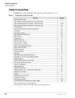
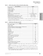
This worksheet helps you configure the system. Use the following tables to record the hardware
that comprises the system. To ensure that the system port/line capacity is not exceeded, consult
Configuration
when you fill out the worksheet tables. After configuring the
system, use Worksheet 2 to ensure that the system power factors are not exceeded.
Be sure to consult
“Example Configuration Tables” on Page 2-14
when filling out these tables.
Customer:
Location:
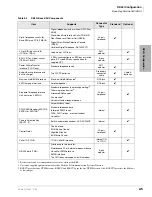
Table 2-10
Hardware Configuration
Base Cabinet
Expansion Cabinet
Slot
No.
00
11
12
13
14
15
16
17
18
PCB
Type
None or
K4RCU3,
K5RCU
or
K5RCU2
8 DKTs
None
None
None
Universal
PCB
Universal
PCB
Universal
PCB
Universal PCB
(except
Stratagy DK)
TCOU
(4 Loop
Start
Lines)
TDDU
(4 DID
Lines)
KSTU2
4 SLT
TCIU2
4 CLID
TBSU
(2 BRI S/
T
Circuits)
TBUU
(2 BRI U
Circuits)
Summary of Contents for Strata AirLink DK40i
Page 22: ...Introduction Related Documents Media xx Strata DK I M 6 00 ...
Page 48: ...DK14 Installation DK14 Wiring Diagrams 1 26 Strata DK I M 6 00 ...
Page 220: ...DK424 Installation Remote Cabinet Installation Instructions 5 68 Strata DK I M 6 00 ...
Page 262: ...DK424i Configuration Primary Reserve Power Cabinet Hardware 6 42 Strata DK I M 6 00 ...
Page 450: ...Universal Slot PCB Wiring Option Interface PCB Wiring Diagrams 10 42 Strata DK I M 6 00 ...
Page 592: ...Peripheral Installation Enhanced 911 Service E911 12 84 Strata DK I M 6 00 ...
Page 616: ...ACD Installation Spectrum Electronic Wall Boards 13 24 Strata DK I M 6 00 ...
Page 634: ...Fault Finding Fault Isolation Flowcharts 14 18 Strata DK I M 6 00 ...
Page 704: ...ISDN Interfaces ISDN Disconnect Cause Code 16 54 Strata DK I M 6 00 ...

