ACD Installation
Spectrum Electronic Wall Boards
Strata DK I&M 6/00
13-23
AC
D Instal
lation
Spectrum Electronic Wall Boards
Electronic Wall Boards can be connected to each supervisor’s PC to display call center status data
over head from the Call Center Viewer application. This provides visibility of important call center
event information to both supervisors and agents. The supervisor can also send custom, user
defined, text information to the electronic Wall Board. This can be used for general information,
motivational messages, etc.
One copy of the Call Center Viewer application supports a Wall Board network which can cover
all active ACD groups. The Call Center Viewer application works with Spectrum 200, 300 and 700
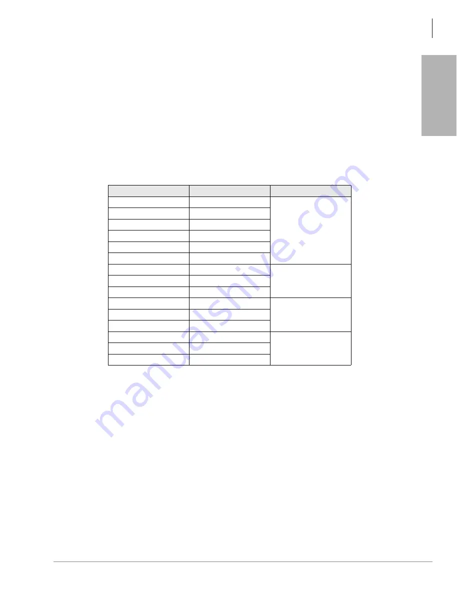
series electronic Wall Boards listed below. In the following table, “R” stands for a red display and
“C” stands for a three-color display: green, amber, and red.
Table 13-1
Wall Board Model and Part Numbers
Spectrum Electronic Wall Boards are available directly from Spectrum Corporation
(800-392-5050 or at Website: http://www.specorp.com). Spectrum provides technical support for
their products. Toshiba does not plan to sell, stock, or provide technical support for Spectrum Wall
Boards.
Multiple Wall Boards
Each Call Center Viewer PC can drive multiple electronic Wall Boards that function independently
from other supervisor’s Wall Boards. Wall Boards connect to each other using a twisted pair
Spectrum network. Up to 255 slave Wall Boards can be attached to one master Wall Board. The
total cable distance can be up to 10,000 feet.
Each supervisor can send custom messages to that supervisor’s Wall Board. The Wall Boards are
addressable so that multiple supervisors can use a group of Wall Boards connected to one PC to
send messages and ACD data differently to each Wall Board.
Model
Toshiba Part Number
Message Area Size
215R Master
TOS1512RM1
27” wide x 2.1” high
215R Slave
TOS1512RS1
215R Stand-alone
TOS1512RA1
215C Master
TOS1512CM1
215C Slave
TOS1512CS1
215C Stand-alone
TOS1512CA1
320C Master
TOS1023CM1
54” wide x 3.1” high
320C Slave
TOS1023CS1
320C Stand-alone
TOS1023CA1
330C Master
TOS1033CM1
81” wide x 3.1” high
330C Slave
TOS1033CS1
330C Stand-alone
TOS1033CA1
714C Master
TOS3417CM1
45.6” wide x 4” high
714C Slave
TOS3417CS1
714C Stand-alone
TOS3417CA1
Summary of Contents for Strata AirLink DK40i
Page 22: ...Introduction Related Documents Media xx Strata DK I M 6 00 ...
Page 48: ...DK14 Installation DK14 Wiring Diagrams 1 26 Strata DK I M 6 00 ...
Page 220: ...DK424 Installation Remote Cabinet Installation Instructions 5 68 Strata DK I M 6 00 ...
Page 262: ...DK424i Configuration Primary Reserve Power Cabinet Hardware 6 42 Strata DK I M 6 00 ...
Page 450: ...Universal Slot PCB Wiring Option Interface PCB Wiring Diagrams 10 42 Strata DK I M 6 00 ...
Page 592: ...Peripheral Installation Enhanced 911 Service E911 12 84 Strata DK I M 6 00 ...
Page 616: ...ACD Installation Spectrum Electronic Wall Boards 13 24 Strata DK I M 6 00 ...
Page 634: ...Fault Finding Fault Isolation Flowcharts 14 18 Strata DK I M 6 00 ...
Page 704: ...ISDN Interfaces ISDN Disconnect Cause Code 16 54 Strata DK I M 6 00 ...


