Fault Finding
Parts Return
14-2
Strata DK I&M 6/00
Faults in the Strata DK40i, DK424 and
DK424i are cleared by replacing PCBs,
telephones (digital or electronic) or the
power supply, as instructed in the
flowcharts.
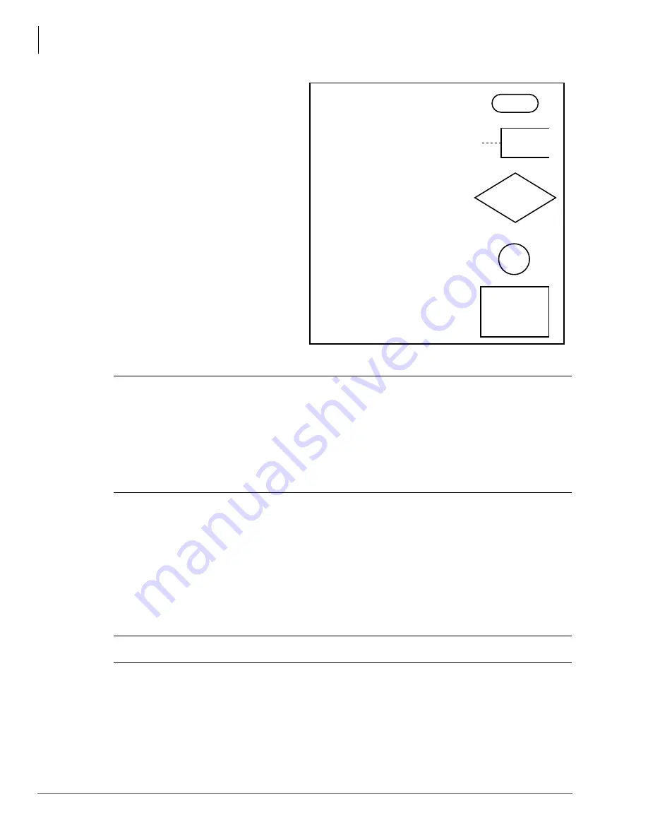
Five symbols are used in the flowcharts,
which are identified in Figure 12-1.
The flowcharts are sequentially
arranged to permit rapid fault
localization within the system. All fault
clearing must begin with the Fault
Classification Flowchart, which is
arranged in the correct fault locating
sequence.
CAUTION!
When handling PCBs, do not:
Drop a PCB.
Stack one PCB on top of another.
Handle a PCB without discharging any static electricity from your person by
touching the grounded cabinet.
Touch the PCB contacts with your fingers.
Important!
If the fault is not cleared by substituting a PCB, reinstall the original PCB in the
KSU/cabinet before trying another PCB.
Parts Return
1. Pack the part in a suitable container (original box is highly recommended). Use anti-static
containers for all PCBs and feature cartridges. Use plastic bags for digital or electronic
telephones, KSU/cabinet, etc.
CAUTION!
To avoid damage, never write on the part itself.
2. Describe the nature of the defect on an information tag. Attach the tag to the front of the unit
with string (not wire) so the tag can remain attached during the testing and repair.
Note
Return tags are available from Toshiba America Information Systems, Inc., TSD Division.
Progression TO or FROM another
flowchart location. Letters and
numbers denote the exact
entrance or exit points.
Important notes affecting the
fault clearing procedure.
Marking points of a
flowchart sequence.
Question to be answered
YES or NO.
Statement of a required action.
1887
Figure 14-1
Flowchart Symbols
Summary of Contents for Strata AirLink DK40i
Page 22: ...Introduction Related Documents Media xx Strata DK I M 6 00 ...
Page 48: ...DK14 Installation DK14 Wiring Diagrams 1 26 Strata DK I M 6 00 ...
Page 220: ...DK424 Installation Remote Cabinet Installation Instructions 5 68 Strata DK I M 6 00 ...
Page 262: ...DK424i Configuration Primary Reserve Power Cabinet Hardware 6 42 Strata DK I M 6 00 ...
Page 450: ...Universal Slot PCB Wiring Option Interface PCB Wiring Diagrams 10 42 Strata DK I M 6 00 ...
Page 592: ...Peripheral Installation Enhanced 911 Service E911 12 84 Strata DK I M 6 00 ...
Page 616: ...ACD Installation Spectrum Electronic Wall Boards 13 24 Strata DK I M 6 00 ...
Page 634: ...Fault Finding Fault Isolation Flowcharts 14 18 Strata DK I M 6 00 ...
Page 704: ...ISDN Interfaces ISDN Disconnect Cause Code 16 54 Strata DK I M 6 00 ...


