Fault Finding
Station Cable Continuity Check
Strata DK I&M 6/00
14-9
Fault
F
inding
Cable Installation Test
If cable voltmeter and ohmmeter tests are within limits, digital telephones, DDCBs, or DDSS
consoles may not operate.
➤
To perform the cable installation test
1. Cable runs for the above digital devices must be free of cable splits (single or double). Test for
and eliminate all cable splits.
2. Cable bridge taps – Digital telephones will not operate if cable runs contain any type (short or
long) of cable bridge. Test for and eliminate all cable bridges.
3. When installing the station cable, do not run parallel to and within 3 ft. of an AC power line.
AC power lines should cross at right (90
°
) angles only. In particular, avoid running station wire
pairs near devices that generate electrical noise, such as neon or fluorescent light fixtures.
4.
For DK40i:
See
. Verify that your telephone is wired correctly (2-pair
or External power) for the options it supports (ADM, RPCI-DI, PDIU-DI, HHEU, DVSU,
etc.).
Table 14-3
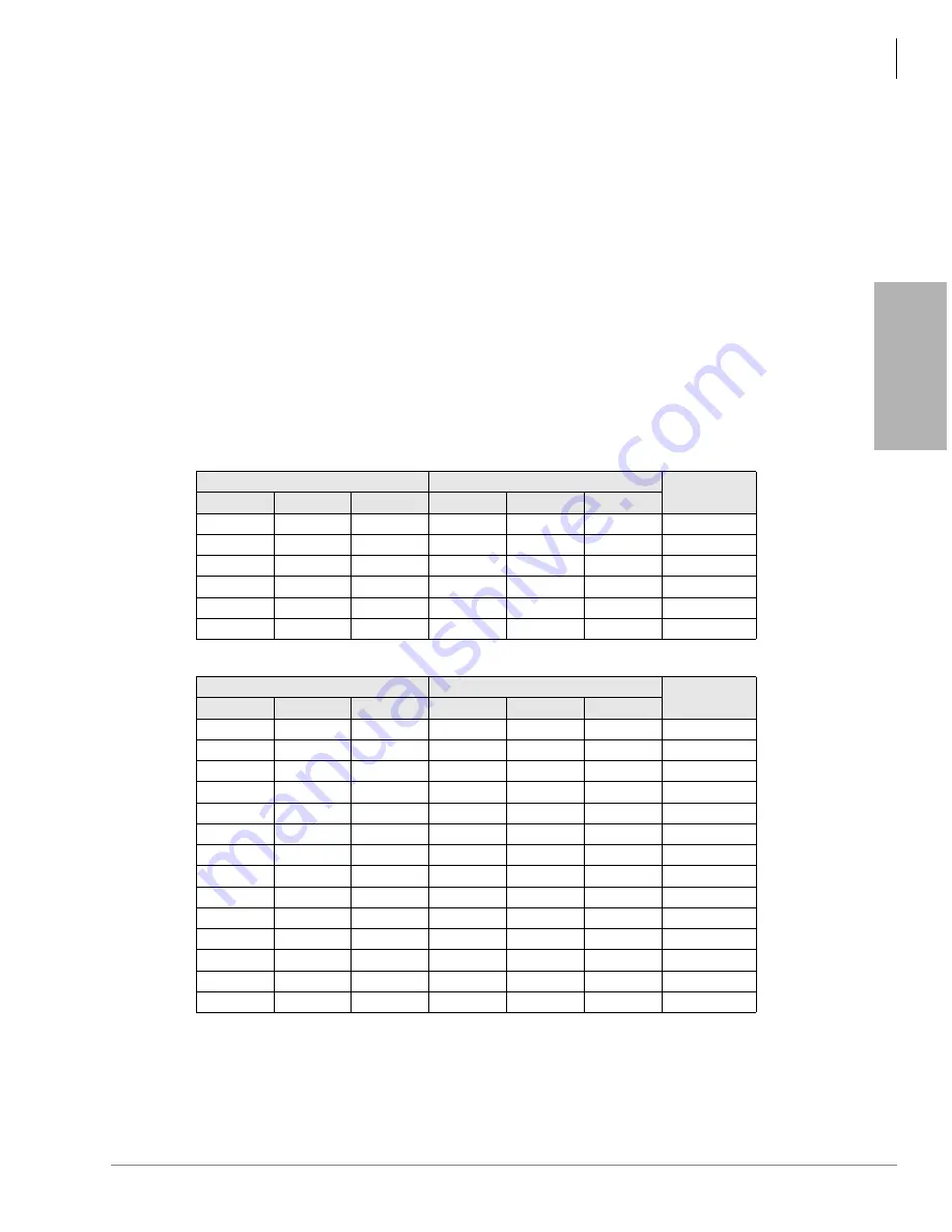
Station Cable Continuity Check for Digital Telephone Cables using Ohmmeter
From
To
Voltage
Pair
Wire
Color
Pair
Wire
Color
1
T
Green
1
2
T
Black
open
1
R
Red
2
T
Black
open
1
T
Green
2
R
Yellow
open
1
R
Red
2
R
Yellow
open
1
T
Green
1
R
Red
40 ohms
2
2
T
Black
2
R
Yellow
40 ohms
2
Table 14-4
Station Cable Continuity Check for Electronic Telephone Cables using Ohmmeter
From
To
Voltage
Pair
Wire
Color
Pair
Wire
Color
1
T
Green
1
1.
The green-red, black-yellow and white-blue measurements should be within 10%
of each other.
2
T
Black
open
1
R
Red
2
T
Black
open
1
T
Green
2
R
Yellow
open
1
R
Red
2
R
Yellow
open
1
T
Green
1
R
Red
40 ohms
2
2.
This is the maximum allowable reading for all digital and electronic telephone
cable runs except if connecting an HDSS console to circuits 7 and 8 of a PEKU,
then the maximum cable restriction is 20 ohms, not 40 ohms.
2
T
Black
2
R
Yellow
40 ohms
2
3
T
White
3
R
Blue
40 ohms
2
3
T
White
1
R
Red
open
3
R
Blue
1
R
Red
open
3
T
White
1
T
Green
open
3
R
Blue
1
T
Green
open
3
T
White
2
T
Black
open
3
R
Blue
2
T
Black
open
3
T
White
2
R
Yellow
open
Summary of Contents for Strata AirLink DK40i
Page 22: ...Introduction Related Documents Media xx Strata DK I M 6 00 ...
Page 48: ...DK14 Installation DK14 Wiring Diagrams 1 26 Strata DK I M 6 00 ...
Page 220: ...DK424 Installation Remote Cabinet Installation Instructions 5 68 Strata DK I M 6 00 ...
Page 262: ...DK424i Configuration Primary Reserve Power Cabinet Hardware 6 42 Strata DK I M 6 00 ...
Page 450: ...Universal Slot PCB Wiring Option Interface PCB Wiring Diagrams 10 42 Strata DK I M 6 00 ...
Page 592: ...Peripheral Installation Enhanced 911 Service E911 12 84 Strata DK I M 6 00 ...
Page 616: ...ACD Installation Spectrum Electronic Wall Boards 13 24 Strata DK I M 6 00 ...
Page 634: ...Fault Finding Fault Isolation Flowcharts 14 18 Strata DK I M 6 00 ...
Page 704: ...ISDN Interfaces ISDN Disconnect Cause Code 16 54 Strata DK I M 6 00 ...


