ISDN Interfaces
RPTU Installation
Strata DK I&M 6/00
16-9
ISDN
Inte
rface
s
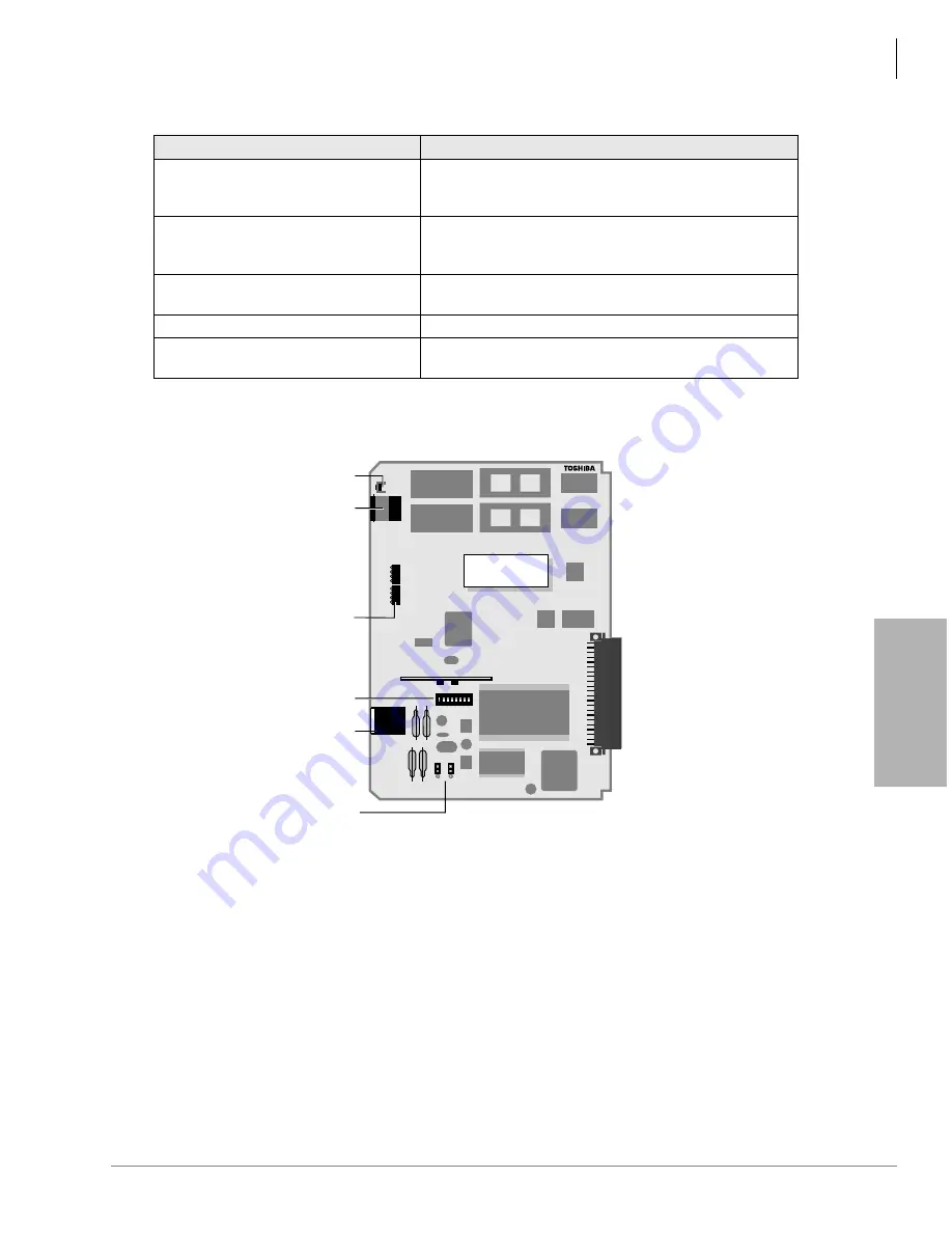
Table 16-7
RPTU Switches, Jumpers, and Connectors
Figure 16-2
RPTU PCB
Switches/Jumpers/Connector
Description
SW1 (Line length adjustment switch)
Matches the RPTU impedance to the impedance of the
line (length between the CSU and the RPTU). Refer to
SW2 (Reset switch)
1
1. If this switch on the Primary Clock source RPTU is pressed (Program *42-1), the clock source will automatically
revert to the Secondary Clock source PCB (Program *42-2).
Resets or initializes the RPTU firmware. Press this switch
to correct an out-of-service condition, or just prior to
connecting to the Network PRI.
JP1 & JP2 (Loop-back jumpers)
Makes loop-back tests of the cabling between the ISDN
Network switch, CSU, and RPTU.
J1 8-pin Modular Connector (RJ45)
Connects the RPTU to the CSU/network PRI ISDN line.
J2 6-pin Modular Connector (RJ11)
Connects the RPTU to a terminal or PC to monitor
D-channel data.
Backplane Connector
2543
RS-232C
RESET
CD2
CD1
FSYC
AIS
RAB
LOS
RST
BSU
TS
RPTU1
RPTU1A
V .1
ISDN (PRI)
JP1
JP2
1 2 3 4 5 6 7 8
OFF
MCC
RPTU1A
(front)
SW2
J2
LEDs
SW1
J1
JP1 & JP2
Summary of Contents for Strata AirLink DK40i
Page 22: ...Introduction Related Documents Media xx Strata DK I M 6 00 ...
Page 48: ...DK14 Installation DK14 Wiring Diagrams 1 26 Strata DK I M 6 00 ...
Page 220: ...DK424 Installation Remote Cabinet Installation Instructions 5 68 Strata DK I M 6 00 ...
Page 262: ...DK424i Configuration Primary Reserve Power Cabinet Hardware 6 42 Strata DK I M 6 00 ...
Page 450: ...Universal Slot PCB Wiring Option Interface PCB Wiring Diagrams 10 42 Strata DK I M 6 00 ...
Page 592: ...Peripheral Installation Enhanced 911 Service E911 12 84 Strata DK I M 6 00 ...
Page 616: ...ACD Installation Spectrum Electronic Wall Boards 13 24 Strata DK I M 6 00 ...
Page 634: ...Fault Finding Fault Isolation Flowcharts 14 18 Strata DK I M 6 00 ...
Page 704: ...ISDN Interfaces ISDN Disconnect Cause Code 16 54 Strata DK I M 6 00 ...


