ISDN Interfaces
RBSU/RBSS and TBSU Interface Units
16-18
Strata DK I&M 6/00
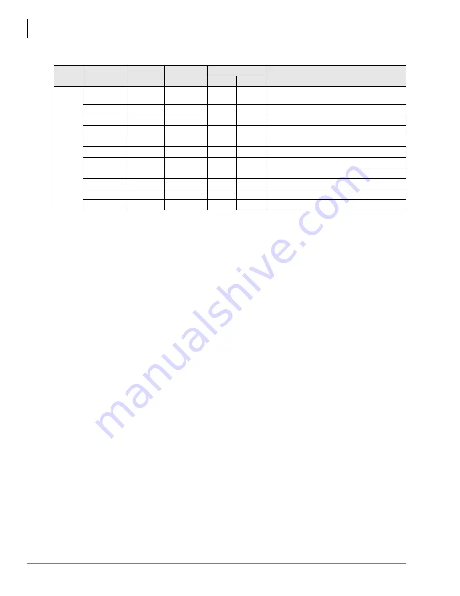
Table 16-10 RBSU/RBSS Option Switches, Jumpers, and Connectors
Step 3: Install the REBS
Note
The REBS provides a basic part of the RBSU/RBSS circuit functionality; therefore, it
must always be installed on the RBSU (see
).
1. Align the two connectors carefully while observing the “UP” arrows on the REBS.
2. Plug the REBS onto the RBSU.
Step 4: Install the RBSS
Note
If one or two additional BRI-NT circuits are required, install the RBSS (see
1. Align the four connectors carefully while observing the “UP” arrows on the REBS.
2. Plug the RBSS onto the RBSU.
Step 5: Install the R40S
Note
If ISDN PS-1 backup power for TE devices is required, install the R40S (optional PCB)
(see
1. Align the two connectors carefully while observing the “UP” arrows on the R40S.
2. Plug the R40S onto the RBSU.
PCB
Circuit
Option
Switch
Type
Circuit Type
Description
TE
NT
RBSU
All
SW 1
Push-button
N/A
N/A
Resets firmware on all circuits of RBSU/RBSS.
Drops calls off the RBSU/RBSS.
1
SW 2
Jumper
X
X
Causes the circuit to operate as TE or NT
1
.
1. Also requires Program *60 to set TE or NT.
1
SW 3
Slide
On
Off
Switches a 100-ohm resistor in/out of the circuit.
1
SW 4, 5
Jumper
N/A
On
Switches PS-1 in/out of the circuit.
2
SW 6
Jumper
X
X
Causes the circuit to operate as TE or NT
1
.
2
SW 7
Slide
On
Off
Switches a 100-ohm resistor in/out of the circuit.
2
SW 8, 9
Jumper
N/A
On
Switches PS-1 in/out of the circuit.
RBSS
3 (NT only)
SW 1
Slide
On
Off
Switches a 100-ohm resistor in/out of the circuit.
3 (NT only)
SW 3, 4
Jumper
N/A
On
Switches PS-1 in/out of the circuit.
4 (NT only)
SW 2
Slide
On
Off
Switches a 100-ohm resistor in/out of the circuit.
4 (NT only)
SW 5, 6
Jumper
N/A
On
Switches PS-1 in/out of the circuit.
Summary of Contents for Strata AirLink DK40i
Page 22: ...Introduction Related Documents Media xx Strata DK I M 6 00 ...
Page 48: ...DK14 Installation DK14 Wiring Diagrams 1 26 Strata DK I M 6 00 ...
Page 220: ...DK424 Installation Remote Cabinet Installation Instructions 5 68 Strata DK I M 6 00 ...
Page 262: ...DK424i Configuration Primary Reserve Power Cabinet Hardware 6 42 Strata DK I M 6 00 ...
Page 450: ...Universal Slot PCB Wiring Option Interface PCB Wiring Diagrams 10 42 Strata DK I M 6 00 ...
Page 592: ...Peripheral Installation Enhanced 911 Service E911 12 84 Strata DK I M 6 00 ...
Page 616: ...ACD Installation Spectrum Electronic Wall Boards 13 24 Strata DK I M 6 00 ...
Page 634: ...Fault Finding Fault Isolation Flowcharts 14 18 Strata DK I M 6 00 ...
Page 704: ...ISDN Interfaces ISDN Disconnect Cause Code 16 54 Strata DK I M 6 00 ...


