DK40i Configuration
Worksheet 2 – System Power Factor Check
Strata DK I&M 6/00
2-19
DK40i Conf
iguration
Worksheet Examples
Note
It is not necessary to consider the 5 volt PF for telephone devices.
Table 2-23
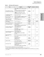
DK40i PCB and Power Factors Worksheet Example
In the following example, the total DK40i PFs, 10.2 PF for the +5VDC PF category and 26.5
TPSU16 m5VDC PF = 14; Maximum -24VDC PF = 39.
Table 2-22
DK40i Telephone/Device 24 Volt Power Factor Worksheet Example (Base/Expansion KSU)
Telephone Devices
Quantity
X
24VDC PF
=
24VDC Total
2000-series Digital Telephone (any series)
16
X
1.0
=
16.0
Cordless Digital Telephone (DKT2004-CT)
X
1.0
=
2000-series Electronic Telephone
X
2.0
=
3000-series Electronic Telephone
X
2.5
=
6000-series Electronic Telephone
X
2.0
=
6005-series Electronic Telephone
X
2.0
=
6500-series Electronic Telephone
X
1.0
=
DDCB/HDCB (w. MDFB)
X
1.2
=
DDSS/HDSS Console
X
0.8
=
Add-on Module
X
0.4
=
RPCI-DI
8
X
0.5
=
4.0
PDIU-DI2 and PDIU-DS
X
0.8
=
Standard Telephone (-48VDC)
X
1.0
=
Standard Telephone (-24VDC)
X
0.5
=
Power Failure Unit (DPFT)
X
3.0
=
HHEU
X
0.1
=
Stratagy DK
X
1.0
=
Total -24VDC PF all Telephone Devices
=
20.0
Base PCBs
PCB Installed
+5VDC PF
-24VDC PF
Yes
No
K5RCU2
X
0.6
NR
K5RCU
X
NR
K4RCU3
X
NR
TSIU
X
NR
TCOU
X
NR
TBSU
X
2.5
NR
KSTU2
X
1.0
NR
TDDU
X
NR
TCIU
X
NR
Expansion Unit PCBs
PCB Name
Slot 15
RBSU (2TE)
2.5
3.8
Slot
16
RBSS (2NT)
0.6
0.3
Slot
17
KCDU
1.5
1.2
Slot
18
KCDU
1.5
1.2
Telephone Devices from
N/R
N/R
20.0
Total DK40i PF =
10.2
1
1. Power factors are within limits. If power factors are exceeded, the system size must be reduced to stay
within PF limits.
26.5
1
Summary of Contents for Strata AirLink DK40i
Page 22: ...Introduction Related Documents Media xx Strata DK I M 6 00 ...
Page 48: ...DK14 Installation DK14 Wiring Diagrams 1 26 Strata DK I M 6 00 ...
Page 220: ...DK424 Installation Remote Cabinet Installation Instructions 5 68 Strata DK I M 6 00 ...
Page 262: ...DK424i Configuration Primary Reserve Power Cabinet Hardware 6 42 Strata DK I M 6 00 ...
Page 450: ...Universal Slot PCB Wiring Option Interface PCB Wiring Diagrams 10 42 Strata DK I M 6 00 ...
Page 592: ...Peripheral Installation Enhanced 911 Service E911 12 84 Strata DK I M 6 00 ...
Page 616: ...ACD Installation Spectrum Electronic Wall Boards 13 24 Strata DK I M 6 00 ...
Page 634: ...Fault Finding Fault Isolation Flowcharts 14 18 Strata DK I M 6 00 ...
Page 704: ...ISDN Interfaces ISDN Disconnect Cause Code 16 54 Strata DK I M 6 00 ...


