DK40i Installation
Printed Circuit Board (PCB) Installation
Strata DK I&M 6/00
3-27
D
K
40
i Installation
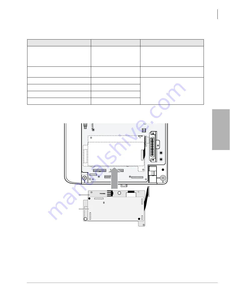
Figure 3-19 KSTU2/KSTS2 Installation
TBSU
“RBSU/RBSS and TBSU Interface Units” on Page 16-13
for
TSBU installation documentation.
Table 3-5
KSTU2 Controls and Interface Connectors
Control/Indicator/Connector
Type of Component
Description
Ring voltage jumper plug SW1
3-terminal jumper
Sets ring generator voltage level for all
circuits:
H = 190V P-P
L = 130V P-P
Connector cable P504
Cable
Connects to P4 connector on the
motherboard
P10 (connects to KSTS2 P20)
7-pin connector
Interface connector for optional
KSTS2. The KSTS2 arrives installed
onto the KSTU2 from the factory.
P11 (connects to KSTS2 P21)
9-pin connector
P12 (connects to KSTS2 P22)
3-pin connector
P13 (connects to KSTS2 P23)
5-pin connector
P4
KSTU
KSTU2A
24/140-3T
KSTU2A
UP
1633
KSTS2A
KSTU2A
Summary of Contents for Strata AirLink DK40i
Page 22: ...Introduction Related Documents Media xx Strata DK I M 6 00 ...
Page 48: ...DK14 Installation DK14 Wiring Diagrams 1 26 Strata DK I M 6 00 ...
Page 220: ...DK424 Installation Remote Cabinet Installation Instructions 5 68 Strata DK I M 6 00 ...
Page 262: ...DK424i Configuration Primary Reserve Power Cabinet Hardware 6 42 Strata DK I M 6 00 ...
Page 450: ...Universal Slot PCB Wiring Option Interface PCB Wiring Diagrams 10 42 Strata DK I M 6 00 ...
Page 592: ...Peripheral Installation Enhanced 911 Service E911 12 84 Strata DK I M 6 00 ...
Page 616: ...ACD Installation Spectrum Electronic Wall Boards 13 24 Strata DK I M 6 00 ...
Page 634: ...Fault Finding Fault Isolation Flowcharts 14 18 Strata DK I M 6 00 ...
Page 704: ...ISDN Interfaces ISDN Disconnect Cause Code 16 54 Strata DK I M 6 00 ...


