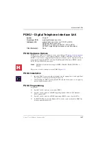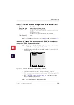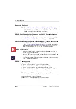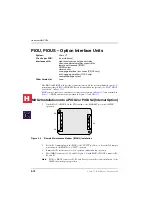
Universal Slot PCBs
3-2
Strata CT I&M Manual October 2000
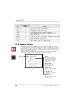
PCB Chapter Layout
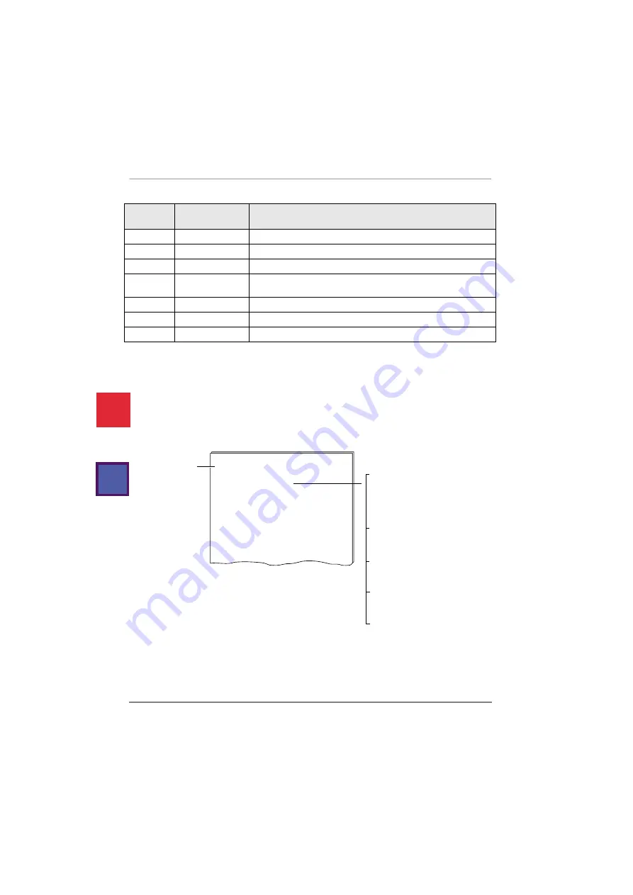
Each PCB outline begins with the PCB’s designation and title (the outline appears in the
chapter in alphabetical order by designation). A brief synopsis of the PCB appears next and
includes a notation of the system(s) that the PCB can be used in, the circuits supplied by the
PCB, what equipment the PCB interfaces with, and a list of the PCB’s older version(s) with a
brief description of their differences.
Installation and programming instructions follow the synopsis with a table showing the
PCB’s controls, indicators and connectors and an illustration of the board.
PACU
X
Four Circuit AC15 Tie Line Interface Unit
RPTU
X
ISDN30 Primary Rate Interface Unit
RBSU
X
ISDN BRA Interface Unit 2-circuit (4 B channels)
RBSS
X
Sub-Assembly for RBSU-supports 2 S-BUS circuits (4 B
channels) - NT only
R40S1A
X
DC40V power supply unit for RBSU1 - supplies PS1 to ISDNTE
RSTU
X
Standard Telephone Interface Unit
R48S
X
Sub-Assembly Unit for RSTU-48Vdc supply
PCB
Compatible with
Strata CT
Function
sample.pg
System:
Strata CT Expansion KSU
Circuits per PCB:
eight standard telephone circuits
Interfaces with:
standard telephones
voice mail ports
off-premises stations
other similar devices
alternate BGM source (circuit 2 only)
auto attendant digital announcer
Compatible Slot(s):
slots 15~18
Older Versions:
PSTU2-190V P-P or 130V P-P W1 jumper
RSTU
Standard Telephone Interface Unit
Universal Slot PCBs
PCB Title
System:
Circuits per PCB:
Gives the type of system that is
compatible with the given PCB. Be
sure to read this information before
attempting to use a PCB with your
system application.
Type and number of circuits
available on the PCB.
Type of line/hardware the PCB can
accept.
Interfaces with:
Describes older version or versions
of the PCB.
Older Version(s):
Only one telephone (or device) can be connected to a RSTU2 port. If more than one telephone
or device is connected to a port or ringing may not function.
Notes
●
For the system to recognise the DTMF tones generated by a standard telephone (or
any other device connected to a standard telephone port), a DTMF receiver Unit
(K5RCU) must be installed on the Strata CT.
●
Most standard telephones and two-wire devices require the 190VP-P level; however,
some devices may experience ring-trip with 190VP-P and should be set for 130 P-P.
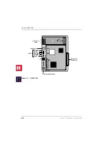
See Figure 3-4 for an illustration of the PSTU2. Figure 3-5 shows the RSTU2. See Table 5-4,
for details of the PSTU and RSTU2 controls and indicators.
Which system slot(s) the PCB can
be installed into.
Compatible Slot(s):
H
C
Summary of Contents for Strata CT
Page 36: ...Strata CT Configuration 1 22 Strata CT I M Manual October 2000 H C ...
Page 94: ...Strata CT Installation 2 58 Strata CT I M Manual October 2000 H C ...
Page 242: ...Peripheral Installation 6 54 Strata CT I M Manual October 2000 H C ...
Page 258: ...ACD Installation 7 16 Strata CT I M Manual October 2000 H C ...
Page 274: ...Fault Finding 8 16 Strata CT I M Manual October 2000 H C ...
Page 364: ...ISDN Interfaces 10 38 Strata CT I M Manual October 2000 H C ...
Page 370: ...Notes to Users A 6 Strata CT I M Manual October 2000 H C ...

