Station Apparatus
Strata CT I&M Manual October 2000
5-21
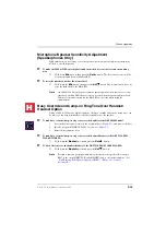
Microphone/Speaker Threshold (Speakerphones only)
High ambient noise levels may cause the speaker on the electronic telephone speakerphone
models (the EKT6510-S, EKT6520-S, and EKT6520-SD) to cut off frequently.
➤
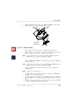
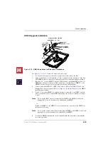
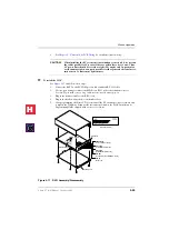
To make these telephones less sensitive to noise and to prevent the cut-off
See
and
and follow these steps:
1.
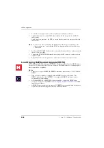
Remove the four captive screws on the base to the telephone, and remove the base.
2.
Locate the room noise switch on the PCB inside the telephone, and push it carefully to
the HI (high) position.
3.
Reinstall the telephone base and secure in place using the four captive screws.
Handset Receiver Volume-up Strap (Version 2 6500-series
Telephones Only)
For Version 2 (V.2) 6500-series electronic telephones only, the handset receiver volume can
be increased six decibels (dB) by cutting a strap inside the telephone.
➤
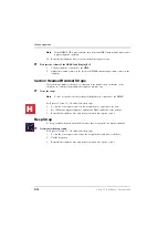
To cut the strap
See
and
and follow these steps:
1.
Remove the four captive screws on the telephone base to the telephone, and remove the
base.
2.
Locate the R-UP strap on the PCB inside the telephone and cut it.
3.
Reinstall the telephone base, and secure in place using the four captive screws.
Direct Station Selection (DSS) Console/System
Connection
◆
B1CAU support up to four DSS consoles
◆
B2CAU/BU, B3CAU/BU, B5CAU/BU up to eight consoles.
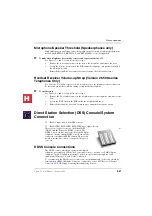
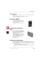
There are two types of consoles: the Digital DSS
(DDSS) and the Electronic (HDSS) console. The
DDSS console can be connected to designated digital
telephone circuits, and the HDSS console can only be
connected to designated PEKU circuits. This section
provides instructions on how to install both types of
consoles.
DDSS Console Connections
The DDSS console, which can operate with a digital
telephone (preferably an LCD model), can connect only to circuit 8 of a PDKU digital
telephone circuit. Standard twisted single-pair or two-pair jacketed telephone cable
(maximum 305 metres) is used for the connection.
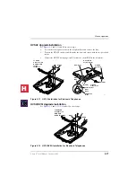
To accommodate the DDSS console connection, the instrument end of the cable should be
terminated in a BS631 Modular Connector connected to a slave LJU. Refer to
for wiring/interconnecting details.
1872
H
C
Summary of Contents for Strata CT
Page 36: ...Strata CT Configuration 1 22 Strata CT I M Manual October 2000 H C ...
Page 94: ...Strata CT Installation 2 58 Strata CT I M Manual October 2000 H C ...
Page 242: ...Peripheral Installation 6 54 Strata CT I M Manual October 2000 H C ...
Page 258: ...ACD Installation 7 16 Strata CT I M Manual October 2000 H C ...
Page 274: ...Fault Finding 8 16 Strata CT I M Manual October 2000 H C ...
Page 364: ...ISDN Interfaces 10 38 Strata CT I M Manual October 2000 H C ...
Page 370: ...Notes to Users A 6 Strata CT I M Manual October 2000 H C ...

