background image

Strata CT Installation

Strata CT I&M Manual  October 2000

2-29

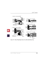
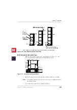
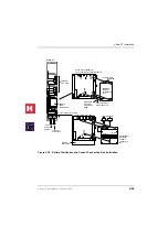
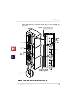
Figure 2-16

Floor Mounting Cabinet Installation

Bolt Cabinets to Concrete Floor

1.

Mount the Strata CT Base Cabinet on Floor Mount Fixtures (see 

Figures 2-15

 and 

2-17

). Position the Base Cabinet at the selected installation location.

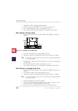
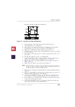
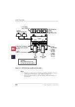
Figure 2-17

Installation on Concrete Floor

2.

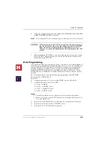
Mark the floor where holes will be drilled. Move the Base Cabinet prior to drilling.

Note

Cover the Base Cabinet with a drop cloth to protect the power equipment from dust 
created during drilling.

3.

Use a hammer drill to make holes for 3/8-inch bolt anchors.

Note     

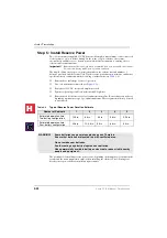
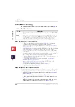
RWBF (3-pairs) and BFIF Stands (1-pair) are supplied with floor installation kit BFIF.

BFIF

BFIF

BFIF

RWBFs are used on left and 
right sides, wherever indicated

BFIFs are used on left and 
right sides, wherever indicated

“A”
Front two 
screws, left
and right sides

“B” 
Back two 
screws, left 
and right sides

A

B

A

B

A

B

A

A

A

B

A

B

A

B

A

B

RWBF

RWBF

RWBF

RWBF

B

B

RWBF

RWBF

RWBF

5007

Concrete

Floor

BFIF

(Floor 

mount 
fixture)

Bottom 
Cabinet

Bolt

Lockwasher

Bolt Anchor

Plug

5242

H

C

Summary of Contents for Strata CT

Page 1: ...October 2000 TOSHIBA TOSHIBA TOSHIBA TOSHIBA Telecommunications Division Installation Maintenance Manual Release 1 Digital Business Telephone Solutions H C ...

Page 2: ...Version 1 October 2000 Copyright 2000 Toshiba Information Systems UK Ltd Telecommunications Division All rights reserved No part of this manual covered by the copyrights hereon may be reproduced in any form or by any means graphic electronic or mechanical including recording taping photocopying or information retrieval systems without express written permission of the publisher of this material St...

Page 3: ...BRI Circuit Capacity Guidelines 1 5 Remote Expansion Cabinet Unit 1 11 Strata CT Hardware Compatibility 1 12 Functional Block Diagrams 1 13 Strata CT Cabinet Slot Configuration 1 16 PCB Placement Guidelines 1 16 Power Considerations 1 19 Reserve Power 1 20 Primary Reserve Power Cabinet Hardware 1 20 Chapter 2 Strata CT Installation Inspection 2 1 Packaging and Storage 2 1 Site Requirements 2 2 Inp...

Page 4: ...hree or More Cabinets Floor Mount 2 35 Install Universal and Processor PCBs 2 35 PCB Installation Considerations 2 36 PCB Option Considerations 2 36 BCU Processor PCBs 2 37 PCB Installation Power Supply Considerations 2 37 Maximum Capacities 2 37 Internal Hardware Options 2 38 BCU Installation 2 40 BCU Programming 2 41 Remote Expansion Cabinet Unit 2 49 Remote Cabinet Installation Instructions 2 5...

Page 5: ...22 PEMU DC5 Tie Line Unit 3 23 PACU AC15 Tie Line Unit 3 26 RSIU RSIS RMDS RS 232 Modem Interface Unit 3 29 RSIS RMDS Piggy Back Installation 3 30 RSIU Installation 3 30 RSIU RSIS RMDS Programming 3 33 PSTU RSTU Standard Telephone Interface Unit 3 35 R48S 48 Volt Supply Installation Internal Option 3 35 External Options 3 36 RSTU2 RSTU3 Installation 3 36 PSTU RSTU Programming 3 38 Chapter 4 Univer...

Page 6: ... 16 Loud Ringing Bell Headset Upgrade HHEU 5 18 Carbon Headset Handset Straps 5 20 Beep Strap 5 20 Microphone Speaker Threshold Speakerphones only 5 21 Handset Receiver Volume up Strap Version 2 6500 series Telephones Only 5 21 Direct Station Selection DSS Console System Connection 5 21 DDSS Console Connections 5 21 DDSS Programming 5 22 HDSS Console 5 22 Door Phone MDFB 5 23 Lock Control Unit and...

Page 7: ...ounting 6 26 T001B Relay Unit Options 6 26 System Hardware Requirements 6 26 T001B Installation 6 27 T001B Relay Unit Test 6 27 External Page Options 6 28 External Page Option Installation 6 28 SMDR Printer Call Accounting Device Options 6 34 SMDR Printout Examples 6 37 SMDR Programming 6 39 SMDR Printer Call Accounting Device Installation 6 39 System Database Printout Using SMDR Port 6 40 Program...

Page 8: ... Tie Incoming Line Calls 7 7 Transfer From Built in Auto Attendant AA to ACD Group 7 8 Transfer From External AA to an ACD Group 7 8 Overflow From an ACD Group Queue 7 8 ACD Group Status 7 9 Agent Ring No Answer Call Treatment 7 10 ACD SMDR Printout Examples 7 11 Insight DK 7 15 Strata CT Requirements 7 15 Reference Information 7 15 Wall boards 7 15 Chapter 8 Fault Finding Fault Classification 8 1...

Page 9: ...23 Miscellaneous Functions 9 23 Extended Services 9 24 Using StrataLink for CTI Connections 9 27 StrataLink Functions 9 28 Software Application Initiated Events 9 28 Telephone System Events 9 30 Tokens 9 33 TeleMagic Link 9 35 Debugging 9 36 Using Goldmine 95 with StrataLink 9 37 Goldmine 95 Installation Guidelines 9 38 Beneficial Options Available in Goldmine 95 9 41 Using ACT 3 0 with StrataLink...

Page 10: ...10 14 Install the R40S1A 10 14 Install RBSU RBSS PCBs into Cabinet 10 14 Modular Jack Pin Configurations 10 15 RBSU RBSS Premise Wiring Guidelines 10 16 Connecting RBSU to Network Side TE Mode 10 18 Connecting RBSU RBSS Station Devices NT Mode 10 19 Timing and Synchronisation 10 22 RPTU Performance Monitoring 10 24 PRI BRI Call Monitoring 10 26 BRI Call Monitor 10 29 SMDR Output for ISDN 10 31 ISD...

Page 11: ...on installed systems Chapter 3 Universal Slot PCBs provides procedures for Strata CT system Printed Circuit Boards PCBs for installation into universal slots It includes installation instructions optional configuration information and wiring and programming considerations for each PCB Chapter 4 Universal Slot PCB Wiring contains point to point wiring diagrams for connection of telephones lines per...

Page 12: ...tion CTI contains CTI TAPI and System Open Architecture Interface information CTI application notes can be inserted here Chapter 10 ISDN Interfaces contains an overview of the ISDN hardware with specific information on the ISDN Primary Rate Interface PRI and Basic Rate Interfaces BRI It includes instructions for installation hardware requirements wiring requirements and some programming considerat...

Page 13: ...ditional DN Arial Bold Represents telephone buttons Courier Shows a computer keyboard entry or screen display Type Indicates entry of a string of text Press Indicates entry of a single key For example Type prog then press Enter Plus Shows a multiple PC keyboard or phone button entry Entries without spaces between them show a simultaneous entry Example Esc Enter Entries with spaces between them sho...

Page 14: ...xplains all the procedures necessary to operate Toshiba proprietary electronic telephones including all LCD features It also includes instructions for using the electronic DSS console Strata CT Electronic Telephone Quick Reference Guide provides a quick reference for frequently used electronic telephone features Strata CT Standard Telephone User Guide explains all the procedures necessary to opera...

Page 15: ...ork A modular design and a choice of four processors also called common control units enables the system to fit a variety of customer needs and capacities The Strata CT can be configured as a single cabinet system that provides capacity of up to 64 Exchange lines and stations combined and can grow to a five cabinet system that provides capacity for up to 432 Exchange lines and stations combined Se...

Page 16: ...OH BGM source interface and connectors to mount optional DTMF receiver PCBs required for some Exchange line types and peripherals as described below Each processor provides an interface for connecting an optional feature key RKYS as described below B3CAU B3CBU and B5CAU B5CBU require a remote maintenance PCB usually installed in slot S101 the remote maintenance PCB is optional for the B1CU and B2C...

Page 17: ...m SMIS and Insight DK with the following feature keys that attach to the processor See Table 1 3 for features provided by RKYS2 4 Table 1 3 RKYS Features Enhanced ACD with MIS data information 1 Built into all Processors as standard Cabinet Slots Base Cabinet The Base Cabinet has two slots reserved for the system processor PCBs and eight universal slots labeled S101 S108 that can accommodate stati...

Page 18: ...stem capacities depends on power consumption of a particular configuration Configurations for a fully expanded system can range from 200 lines or 336 stations One universal slot is required for Remote Maintenance PCB with B3CAU B3CBU and B5CAU B5CBU but is optional for B1CU and B2CAU B2CBU A summary of the maximum number of lines and stations by processor is shown in Table 1 4 Table 1 4 Strata CT ...

Page 19: ... BRI line circuits to connect to the ISDN Exchange line Each circuit provides two Exchange line channels to the Strata CT 3 Each BRI circuit provides two B channels plus one D channel and reduces the system capacity by two station ports and two Exchange lines regardless of how it is configured line or station Each N T BRI station circuit allows up to two TE 1 and TA devices to share the BRI B chan...

Page 20: ... 700 DTMF receivers 12 24 24 24 External Page Zones 4 4 4 8 Call Park Orbits general 20 20 20 20 Call Park Orbits individual 80 240 240 336 Personal LCD Messages per DKT1 1 Personal Messages includes timed reminder memo and station speed dial memo 10 10 10 10 Personal Message DKTs 32 96 96 96 PhDNs per System 80 240 240 336 PDNs per System 56 144 192 336 Ring Tones 3 3 3 3 Simultaneous Party Confe...

Page 21: ...18 28 48 Exchange lines 32 120 120 200 Table 1 7 Station and Peripherals Capacities Strata CT Capacities Stations B1CU B2CAU B2CBU B3CAU B3CBU B5CAU B5CBU Add on modules DADM 40 120 120 200 Attendant consoles 2 4 4 4 Door locks 5 5 5 5 Door phones 12 12 12 12 DSS consoles 4 8 8 8 Handset OCA stations 56 144 192 336 Off premises stations 48 136 184 328 PCIU used for TAPI only per system 1 56 144 19...

Page 22: ...ne Provides interface for electronic telephone to receive OCA HHEU 2000 series Digital Telephones 6500 series Electronic Telephones Provides interface for headset and Loud Ringing Bell to telephone Can be installed with DVSU PCIU or DADM DADM1 2000 2500 series Digital Telephones Provides telephone with 20 or 40 with two DADMs additional feature buttons for DSS System or Station Speed Dial or Excha...

Page 23: ...modem for DK Admin 1 per PIOU PIOUS None RSTU2 3 8 standard telephone circuits Standard telephones Voice mail ports Off premises stations Other similar devices Alternate BGM source Auto Attendant digital announcer Message Waiting lamp RSTU2 3 only Fax machines ACD Announcer Strata Airlink wireless telephones 25 pair amphenol All PCB amphenol connectors are female RATU 4 PC Attendant PC Console cir...

Page 24: ... printer or call accounting machine PC or maintenance terminal local or remote One 3 pair modular TTY SMDR SMDI SMIS attaches to RSIU RSIS RS 232 interface RMDS Modem RS 232 Up to 3 RSISs or 1 RMDS and 2 RSISs per RSIU Provides up to four interface ports RS 232 and modem for system interface with RMDS 1200 or 2400 bps Voice Mail SMDI ACD SMIS SMDR Local or Remote Maintenance for DK Admin or DK Bac...

Page 25: ...nes X Unamplified page output single zone 600 ohms duplex X X X Amplified page output single zone 3 watts 8 ohms X X Night transfer or Music on hold control relay X X X Door lock or external amplifier control relay X X X Alarm Sensor X X Remote maintenance modem subassembly IMDU or RMDS disables TTY output when they are piggy backed onto the PIOU PIOUS or RSIU RSIS cards 2 X IMDU X IMDU X RMDS Rem...

Page 26: ...Unit RSIU X PIOU X RSSU X PIOUS X Terminal DKT2000 X DKT2500 X EKT6500 X HDSS X Existing Proprietary Attendant Console X Strata CT PC Attendant WOC X RPCI RS 232C TAPI X Base Cabinet DKSUB424F NC CHSUB672F X Expansion Cabinet DKSUE 424F NC CHSUE672F X Power Supply Unit BPSU672F 240VAC power supply X Battery Distribution Box RBDB1A new Battery Distribution Box X Power Strip DK MAINS CON 4 NC 7925 P...

Page 27: ... Lock or BGM Mute Control Relay External Zone Page Relays 4 Zones External Page Amplifier 600Ω Output Music Source Background Music and or Music on hold MOH BGM Volume Control Main Distribution Frame MDF MOH BGM RCA Jack Alarm Relay Sensor Night Bell or MOH Control Relay Battery Charger 12V Battery 12V Battery Twisted Pair 1 Customer supplied equipment RKYS Option Key AA ACD MIS 2 or 4 Batteries B...

Page 28: ...1 per circuit U T PACU 4 AC15 Tie Lines PCOU Analogue Exchange lines 8 wire Modular Jacks 8 wire Modular Jacks Network Demarcation Point Remote Location s Remote Location s BVPU Voice Over IP Unit 4 Circuits PDKU RRCU Remote Cabinet Interface Card Optical Fiber Cable 3 km 1 86 mi Expansion Cabinets Digital Telephone 10BaseT Router MCK Extender MCK Gateway ISDN or IP Network 4272 CT I M Exchange Li...

Page 29: ... pair Modular Cords DPFT Voice Mail Modem RS 232 Cables HESB Loud Ringing Bell Electronic Telephone EKT Door Phones and Lock Controls Standard Telephone Modular Jacks Main Distribution Frame MDF 25 pair Amphenol Connectors and Cables except RBSU RBSS PC Attendant Console EKT with HDSS Console PEKU Only Power Failure Transfer Unit Power Failure Standard Telephone 8 max Off premises Station Digital ...

Page 30: ...at meets the requirements of the configuration can be selected Use the numbered step sequence as a guide beginning with 1 Programming Telephone Interface Main Location _______________ Remote Location 1___ 2___ 3___ 4____ Strata CT Cabinet Slots Base B1011 1 B101 B102 processor slots S101 RSIU PDKU or PEKU slot B1021 S1011 S102 S1032 S104 S1052 2 RPTU allowed slots The adjacent slot must be vacant ...

Page 31: ...tem below 2 Option PCBs for Paging Remote Maintenance ACD SMIS SMDR RS 232 Interface RSIU with without RSIS or RMDS This PCB must be installed if needed in Slot S101 only If RSIU is installed in S101 then a PDKU or PEKU must be installed in S102 to accommodate the programming telephone PIOUS PIOU PEPU each requires one slot These PCBs should be installed after all other PCBs are installed They can...

Page 32: ... cabinets are in separate remote locations 3 4 4 cabinets if cabinets are in separate remote locations 4 Table 1 12 Remote Cabinet Data Cables and Connectors Data Cables RRCU Connectors M1 S1 M2 S2 BDCL1A MS1 X X BDCL1A M2 X BDCL1A S2 X X applies to connector Table 1 13 RPTU PCB Cabinet Slot Configuration PRI Lines Needed Slots Needed RPTU PCBs Needed1 1 RPTU PCBs do not have to be installed in th...

Page 33: ...e 1 13 Each PCB provides up to four circuits for the type of lines it supports 8 ISDN BRI Digital Line PCBs RBSU with RBSS Each PCB RBSU RBSS PCB requires one slot These PCBs can not occupy a slot that is left vacant to provide capacity for RPTU as shown in Table 1 13 Only the RBSU PCB provides 2 BRI circuits four lines Each ISDN BRI circuit provides two lines for the CT system Power Consideration...

Page 34: ...licensed electrician If more than two cabinets require reserve power batteries the BBDB must be installed Wall mounting the system does not require special hardware Local electrical codes require certain standards for connecting commercial AC and reserve power to the Strata CT system Table 1 17 describes which assemblies may be required to meet local electrical code standards Important See EMC Com...

Page 35: ...nnects the Strata CT cabinet power supply directly to the battery terminals a BBDB is not required BBDB Strata CT reserve power battery distribution box is required when connecting reserve power batteries to three or more cabinets wall or floor mount The box is field installed into one of the Strata CT cabinet side panels The BBDB provides five BBTC2A 2 0M battery distribution cables to connect re...

Page 36: ...Strata CT Configuration 1 22 Strata CT I M Manual October 2000 H C ...

Page 37: ... After unpacking and before installing check the system against the packing list and inspect all equipment for damage If equipment is missing or damaged contact your supplier immediately Be sure to retain original packaging materials for re use when storing or transporting system hardware Packaging and Storage CAUTION When handling installing removing examining PCBs do not touch the back soldered ...

Page 38: ...ected to the Strata CT to serve as a backup in case of power failure Separate reserve power may be required for remote expansion cabinets Clearance and Location The Base and optional Expansion Cabinets may be either floor or wall mounted Figure 2 1 shows the minimum clearance requirements for up to five cabinets Notes Floor mounting requires the following additional hardware BFIF floor mounting st...

Page 39: ... required for future growth of up to 7 cabinets 24 24 55 3 Wall Floor Wall Wall Front View Top View 26 5 Cabinets 36 26 5 55 is minimum height requirements for Floor Mounting 5 cabinets 75 is required to allow for future growth of up to 7 cabinets 3 Floor Mount Stands BFIF 2 Brackets RWBF 5005 Expansion Cabinet Expansion Cabinet Expansion Cabinet Expansion Cabinet Base Cabinet Expansion Cabinet Ex...

Page 40: ... to Users Table 2 1 Strata CT Electrical Characteristics Strata CT Primary AC Power Voltage Input AC AC Frequency Watts per cabinet continuous Watts for five cabinet system 240 20VAC 50 60 Hz Single phase 180 900 Strata CT Primary Power Current Consumption Rating in Amperes 240VAC 1 cabinet 2 cabinets 3 cabinets 4 cabinets 5 cabinets 2 0 amps 4 0 amps 6 0 amps 8 0 amps 10 0 amps Power Supply Unit ...

Page 41: ...ght approximates a cabinet completely filled with PCBs Weight may vary slightly depending on PCBs Recommended Installation Sequence Note Each cabinet requires four wood screws 12X 1 25 inch size for wall mount installation Wood screws are not provided with the system Step Reference Information 1 Install power supplies in cabinets Install Power Supply on Page 2 6 2 Mount cabinets on wall or floor W...

Page 42: ...crews 7 If the cabinet is the Base Unit a standalone Remote Expansion Cabinet or the first in a stack of Remote Expansion Cabinets Set the Exp Base switch to the Base position see Figure 2 2 8 If the cabinet is an Expansion Unit set the Exp Base switch to the Exp position Important The power supply set as Base is the master and has On Off control over all other power supplies which are designated ...

Page 43: ...nsert the AC plug back into the wall outlet and turn the DC power switch On The AC and DC LEDs should turn on and the system should operate If the system fails to operate either the wall outlet is not providing AC power or the system s power supply is defective 3 If the AC power checks good replace the power supply Case 2 If the power supply AC and DC LEDs light but the system does not operate the...

Page 44: ...TT DC OUT 27V1 27V2 27V3 27V4 POWER ON OFF FG B101 B102 S101 S102 S103 S104 S105 S106 S107 S108 5039 AC IN BATT 24V1 24V2 24V3 24V4 POWER ON OFF POW 5V 5V P F RESET EXP BASE DC OUT FG DC Voltage Connector Jack DC Voltage Specification 5V 4 5 5 5 4 0 amps 5V 4 5 5 5 0 8 amps Expansion Cabinet only 24V 26 3 27 8 6 0 amps BATT Volts 0 26 3 27 8 1 Back Plane DC Voltage Plug must be plugged into Power ...

Page 45: ...nt cover slides left and the side covers swing out and down for removal 3 Hold the Base Cabinet back cover against the wall or backboard so that its two top mounting holes are approximately 6 1 2 feet 78 inches above the floor This allows up to five cabinets to be installed top down with a six inch clearance between the floor and bottom cabinet see Figures 2 5 and 2 6 4 Use a level to make sure th...

Page 46: ... hangers Slide the cabinet to the right to the proper mounting position and secure the cabinet to the back cover with two screws to the right side of the back cover Repeat for all other Expansion Cabinets 5 Loosen the bonding connection plates fastened on both sides of the first Expansion Cabinet see Figure 2 8 then fasten the plates between the Base Cabinet and the first Expansion Cabinet Repeat ...

Page 47: ...Back Cover 6 inches between bottom cabinet and floor Plaster Board Wall Dealer Supplied 12 X 1 25 Wood Screws 4 Screws Per Cabinet 12 X 1 25 Wood Screws As many as necessary to secure plywood backboard 3 4 Plywood Backboard Floor 5040 Locating Parts 5 0 ft minimum for 5 cabinets or 6 5 ft for 7 cabinets H C ...

Page 48: ...ws to remove back cover Loosen two screws to remove the side cover right and left covers 5041 5038 R i g h t F r o n t Right Side Cover Top Cover Base Cabinet Only Front Cover Loosen two screws to remove front cover Loosen two screws to remove the side covers right and left side covers Loosen four screws to remove the top cover Note Do not remove the top cover if the Base Cabinet is the top cabine...

Page 49: ...re 2 6 Strata CT Mounting Cabinet on Back Cover 18 8 IN 9 9 IN Back Cover Trace Upper Arch Marking Hole 1459 1460 Important After mounting cabinet to back cover use two screws to fasten cabinet to back cover Hanger Back Cover Mounting Strip Hanger Hole Back Cover Hang cabinet on back cover then slide to right H C ...

Page 50: ...IN AC IN DC OUT 27V1 27V2 27V3 27V4 POWER ON OFF FG 5002 POW 5V 5V P F RESET EXP BASE AC IN BATT DC OUT 27V1 27V2 27V3 27V4 POWER ON OFF FG 5002 S201 S202 S203 S204 S205 S206 S207 S208 S209 S210 CABINET NO 2 S201 S202 S203 S204 S205 S206 S207 S208 S209 S210 3 4 5 6 7 POW 5V 5V P F RESET EXP BASE AC IN AC IN DC OUT 27V1 27V2 27V3 27V4 POWER ON OFF FG 5002 POW 5V 5V P F RESET EXP BASE AC IN BATT DC ...

Page 51: ...r Figure 2 8 Figure 2 8 Data Cables Shown in Cabinet Interior Side View To MDF Left Side Bonding Connection Plate required for all wall mount expansion cabinets Remote Cabinet Cable feed through hole PCB Cable Front Data Cables CAB 2 CAB 3 CAB 4 CAB 5 CAB 6 CAB 7 Cable Guard Screw Cable Guard Data Cable Door shown open Expansion Cabinet Cab 2 Cable 5342 H C ...

Page 52: ...inet Amphenol Cables Front Cable Shield B50MT 1 Attach lead to grounding screw 2 Wrap mesh around communication cables 3 Secure with velcro strap CAUTION Mesh strap should not touch cabinet metal surfaces Part No B50MT comes with the Base Cabinet It must be ordered separately for each Remote Cabinet pair 25 Pair Amphenol Cables 5045 To MDF Knock Out Plastic To MDF Top 25 Pair Amphenol Cables H C ...

Page 53: ... primary AC power outlet must be dedicated and must be routed through the same conduit as the phase conductors serving the system The conductor connected to the frame ground FG screw on the system power supply must be insulated and comply with the general rules for grounding contained in ie Regs 16th Edition but must not depend on the cord and plug of the system If the Strata CT system consists of...

Page 54: ...FG Screws Power Supply FG Frame Ground Screws The Single Point Ground must always be connected to the Base Cabinet Power Supply FG Screw Expansion Cabinets Inter cabinet green wires supplied with each cabinet Green Green Yellow ground wires from Motherboard Earth Ground AWG 6 Wire minimum Length 60 Feet maximum Per General Rules IE REGS 16th Edition BMEP Third Wire AC Ground Insulated Ground Wire ...

Page 55: ...are as described in cabinet AC power distribution below AC Reserve Power and Data Cabling Overview Figure 2 11 shows an overview of the AC power and data cabling for the Strata CT Detailed illustrations of AC power strips and cords are on the following pages Figure 2 11 Intercabinet Power Data Cables Motherboard BPSU672A BATT AC IN BPSU672A BATT AC IN BPSU672A BATT AC IN BPSU672A BATT AC IN BPSU67...

Page 56: ... Panel Cabinet Bonding Plate 5219 WARNING To prevent serious injury always mount power strips with provided screws before inserting plug into AC power BPSB240 BPSB240 CAB 5 CAB 4 CAB 3 CAB 2 CAB 1 BASE DK Mains CON 4 DK Mains CON 4 To AC mains CAB 4 CAB 3 CAB 2 CAB 1 BASE DK Mains CON 4 To AC mains AC Cabling CT I M 4 3 2 1 Mains Input E L N DK Mains CON 4 FIVE CABINET INSTALLATIONS FOUR CABINET I...

Page 57: ...Strips in Cabinet Interior To AC Outlet Right Side Bonding Connection Plates Required for all wall mounted expansion cabinets on both right and left sides AC Power Cables Front 7925 P All Power Strip cords are 9 feet long 5233 240 VAC power supply cord is shipped with each cabinet H C ...

Page 58: ...ries are 12VDC rated at 80 amp hours each System is operating at full load traffic with LCD phones Batteries used for this test are gel cell and maintenance free Reserve duration will vary depending upon battery type age and manufacturer These figures should only be used as an estimate Table 2 4 Typical Reserve Power Duration Estimate The procedure for installing reserve power varies depending on ...

Page 59: ...supply BATT receptacle 5 Repeat Steps 3 and 4 to connect a PBTC 3M to the Expansion Cabinet Table 2 5 Reserve Battery Cabinet Components Cables Option Description PBTC 3M A three meter battery cable used to connect reserve power batteries to the system power supply when the system has less than three cabinets One reserve power cable is required for each cabinet in a one or two cabinet system wall ...

Page 60: ...open positive terminal of the 12VDC battery Connect the black lead to the open negative terminal of the second 12VDC battery 5 Connect a second BBTC1A 2 0M in parallel to the first BBTC1A 2 0M cable per Steps 2 3 and 4 instructions 6 Plug the two BBTC1A 2 0M battery cables into the Battery Distribution Box Important The cabinets must be connected to the live AC power source and the power supply On...

Page 61: ...PSU672 BATT connnector BPSU672 BATT connnector BPSU672 BATT connnector BPSU672 BATT connnector 4 Batteries 2 Cabinets without BBDB 2 Batteries 2 Cabinets without BBDB 10A Fuse PBTC 3M Cables 9 ft 10A Fuse Expansion Cabinet Base Cabinet Base Cabinet Expansion Cabinet Base Cabinet PBTC 3M Cables 9 ft 12 Volt Batteries 80 AMP HR Each 12 Volt Batteries 80 AMP HR each BATT BBDB C Cable supplied with BB...

Page 62: ...ground wiring AC and reserve power cabling and PCB cabling per the Recommended Installation Sequence on Page 2 5 8 Fill out cabinet slot identification labels on cabinet s Figure 2 7 9 Reinstall covers on to cabinets Figure 2 4 Floor Mounting Three or More Cabinets This section shows you how to mount three or more cabinets to a concrete wood or computer room floor Use the General Steps for all of ...

Page 63: ...omputer room floor 9 Add remaining cabinets making sure that the cabinets are connected together at points A and B with the screws provided 10 For systems with four or more cabinets make sure that wall brackets RWBF are installed on both sides of the top cabinet in addition to cabinet three 11 Check to make sure the cabinets are parallel to the wall Secure the floor fixtures attached to the bottom...

Page 64: ...ure BFIF must be fixed to floor by either anchor bolts or wall by RWBF wall brackets see Figures 2 15 and 2 16 A B Front 2 Mouting Screws Provided with BFIF Kit Top Cabinet Wall Securing Brackets RWBF Left and Right Side Back 2 Mounting Screws Provided with BFIF Kit B B B B Bottom Wall Securing Bracket RWBF Third Cabinet Wall Securing Bracket RWBF Left and right side B B A A A B BFIF Mounting Scre...

Page 65: ... the Base Cabinet with a drop cloth to protect the power equipment from dust created during drilling 3 Use a hammer drill to make holes for 3 8 inch bolt anchors Note RWBF 3 pairs and BFIF Stands 1 pair are supplied with floor installation kit BFIF BFIF BFIF BFIF RWBFs are used on left and right sides wherever indicated BFIFs are used on left and right sides wherever indicated A Front two screws l...

Page 66: ...o make insertion of 3 8 inch lag bolts easier and to prevent splitting of wood flooring 5 Move the Base Cabinet into position on the equipment room floor 6 Secure the Base Cabinet to the floor using lag bolts lock washers and flat washers Bolt Cabinets to Computer Room Floor 1 Mount the Strata CT Base Cabinet on Floor Mount Fixtures BIMF See Figures 2 15 and 2 16 2 Position the Base Cabinet at the...

Page 67: ... that cabinet power supplies BPSU672A are installed per Install Power Supply on Page 2 6 17 Remove front side and top covers from all cabinets Figure 2 4 Note As shown in Figure 2 4 the two screws on each side cover and the three screws on the front cover the bottom left screw must be completely removed should only be loosened and the covers slid to the right for removal 18 Remove plastic locating...

Page 68: ... Expansion Cabinet to the applicable data cable connector on the Base Cabinet Figures 2 8 and 2 11 The data cable from the first Expansion Cabinet should be connected to the connector labelled CAB 2 the cable from the second Expansion Cabinet to the CAB 3 connector etc 26 Install ground wiring AC and reserve power cabling and PCB cabling per the Recommended Installation Sequence on Page 2 5 27 Fil...

Page 69: ...upply BATT Jack BBTC2A 2M Five Cables Supplied with BBDB BCCB120A or BCCB240 Conduit Connection Box AC Power Battery Cables to BBDB1A Floor Mounted Bottom Cabinet Bottom Cabinet Wall Mount Second from Bottom Cabinet Floor Mount BPSB240A Power Strips BBDB1A Battery Distribution Box 240 Conduit Connection Box Conduit Primary AC Power Pannel Reserve Batteries BFIF Floor Mount Stand Strata CT Floor Mo...

Page 70: ... customer supplied commercial battery box or enclosed rack To BBDB Battery Distribution Box F1 F4 Battery Fuses 250VAC 15A BCCB BATT AC N L Battery Wire Specifications 10 AWG minimum 2 pairs 42A max AC Wire Specifications BCCB120 10 AWG 29A max BBCB240 12 AWG 18A max BCCB240 top view 2 outlets Not Fused Rated 250VAC 20A 5047 F3 F1 F4 F2 Conduit Holes to 1 2 inch trade size WARNING BCCB conduit box...

Page 71: ...function 5 Connect cables from the BBDB Battery Distribution Box to the BATT receptacle of individual power supplies BBTC2A 2M cables come with each BBDB distribution box see Figure 2 11 6 To test reserve power operation turn off the system AC power circuit breaker with power supply On Off switches in the On position The system should continue to operate without interruption See Install Reserve Po...

Page 72: ...ee the Strata CT Configuration and Universal Slot PCB section for details regarding PCB installation PCB Option Considerations Strata CT PCBs can be configured for a variety of hardware and software options Hardware options are defined as either internal generally related to optional PCB subassemblies or external related to connection of peripheral equipment such as background music voice mail etc...

Page 73: ...ystem MIS for ACD Toshiba proprietary RS 232 and SMDI voice mail interfaces PCB Installation Power Supply Considerations 1 The power supply must be Off whenever removing or installing the processor PCB B1CU B2CAU B2CBU B3CAU B3CBU and B5CAU PCBs see Figure 2 2 2 It is recommended that the power supply be Off whenever possible when removing or installing the other PCBs Maximum Capacities Configurat...

Page 74: ...nstalled However configuration programs for AA and ACD must be run for the feature to operate Music on hold Background Music Volume Control External Options Each of the common control units except B2CBU B3CBU and B5CBU has a trim potentiometer VR1 to adjust the volume of the MOH BGM source connected to the Music on hold MOH Background Music BGM RCA jack interface which is also on the common contro...

Page 75: ...rcuits To install an BRCS onto B1CU B2CAU B2CBU B3CAU B3CBU or B5CAU B5CBU Mate BRCS connectors see Figure 2 22 with the applicable BCU PCB Apply firm even pressure to the BRCS to ensure proper mating of the connectors Connectors for each BCU card are shown on Figures 2 22 2 30 One BRCS 4 8 or 12 can be installed on each processor allowing up to 12 DTMF receivers on B1CU and 24 on all other proces...

Page 76: ...or the appropriate hardware options i e BRCS or RKYS See Internal Hardware Options on Page 2 38 3 Insert the B1CU B2CBU B3CBU or B5CBU 1 2 or 3 into the B101 slot in the Base Cabinet If B1CU and RSIU is installed you must also install a ribbon cable between them Figure 2 23 Figure 2 23 Processor PCB Connectors and RSIU Placement Ensure the component side of the BCU PCB is facing right when install...

Page 77: ...ing Program 91 9 twice before all other PCBs are installed If RAM contains configuration or feature data from previous programming that should be retained do not run Program 91 9 See the Strata CT Programming Manual If installing a BCU PCB perform a processor RAM test with Program 00 part 2 On new BCU installations run the RAM test after BCU initialisation before entering the customer database The...

Page 78: ...eceiver Connector P5 6 pin male connector Interface connector for optional DTMF receiver subassembly BRCS BATT Battery Jumper P8 3 terminal jumper Interface connector for on board lithium battery that protects configuration data stored in system RAM MOH BGM Source Connector RCA jack Interface connector for MOH BGM source MOH BGM Source Volume Control VR1 Trim potentiometer Adjusts volume for MOH B...

Page 79: ... BRCS Connector P10 Connector for ribbon cables Ribbon cable connector for connection to B2CBU Connector P11 Connector for ribbon cables Ribbon cable connector for B2CBU and RSIU BATT P9 3 terminal jumper Interface connector for on board lithium battery that protects configuration data stored in system RAM MOH BGM Source Connector RCA jack Interface connector for MOH BGM source MOH BGM Source Volu...

Page 80: ...bles Ribbon cable connector for connection to B2CAU Connector P3 Connector for ribbon cables Ribbon cable connector for B2CAU and RSIU Heart Beat indicator CD5 Red LED Flashes to indicate operation 1 4 second On 1 4 second Off BATT P9 3 terminal jumper Interface connector for on board lithium battery that protects configuration data stored in system RAM MOH BGM Source Connector RCA jack Interface ...

Page 81: ...CBU ribbon cables Ribbon cable connector for connection to B3CAU Used in conjunction with P2 Connector P11 Connector for B3CBU ribbon cables Ribbon cable connector for connection to B3CBU Used in conjunction with P2 BATT P9 3 terminal jumper Interface connector for on board lithium battery that protects configuration data stored in system RAM MOH BGM Source Connector RCA jack Interface connector f...

Page 82: ...Connector P10 Connector and ribbon cable Ribbon cable connector for connection to B3CAU Connector P11 Connector and ribbon cable Ribbon cable connector for B3CAU RSIU BATT Battery Jumper P9 3 terminal jumper Interface connector for on board lithium battery that protects configuration data stored in system RAM MOH BGM Source Connector RCA jack Interface connector for MOH BGM source MOH BGM Source V...

Page 83: ... Connector P3 Connector and ribbon cable Ribbon cable connector to B5CBU Connector P4 Connector and ribbon cable Ribbon cable connector to B5CBU RSIU BATT P9 3 terminal jumper Interface connector for on board lithium battery that protects configuration data stored in system RAM MOH BGM Source Connector RCA jack Interface connector for MOH BGM source MOH BGM Source Volume Control VR1 Trim potentiom...

Page 84: ...MF receiver subassembly BRCS Connector P2 Connector and ribbon cable Ribbon cable connector to B5CAU Used in conjunction with P2 Connector P3 Connector and ribbon cable Ribbon cable connector to B5CAU and RSIU Used in conjunction with P3 Heart Beat Indicator CD5 Red LED Flashes to indicate operation 1 4 second On 1 4 second Off BATT Battery Jumper P5 3 terminal jumper Interface connector for on bo...

Page 85: ...it back to its original form and applies it to a ribbon Data Cable connected to the Remote Expansion Cabinet See Figure 2 31 This is a hardware solution and has no effect on software or administration Remote cabinets support all line and trunk interfaces Network clock signals can only be derived from digital trunks installed in the Base Cabinet Master location RRCU1A cards are used at both the Bas...

Page 86: ... RRCU cards are installed must be modified to protect the routing of the cables through the cabinet Attach the plastic guide to the bracket provided with the RRCU1A card See Figure 2 33 Attach the bracket to the inner wall of the cabinet 4 Install the RRCU Card Select correct jumper options see Figure 2 34 On the Master side both option plugs connect the centre pin to the upper pin M1 M2 On the Sl...

Page 87: ... the Base Cabinet attach an BDCL1A data cable from the data cable connector at the left of the cabinet to Connector M1 or M2 on the RRCU card Cables are provided according to the connectors on the RRCU card to which they are attached see Table 2 15 The cabinet connected to M1 in the base emerges on connector S1 of the RRCU1A at the Remote Expansion Cabinet The cabinet connected to connector M2 of ...

Page 88: ...binet for ease of maintenance Observe the minimum bend radius of 30mm 9 Restore power 10 Run Command Program 91 1 Automatic PCB Recognition and Port Renumber The RRCU PCB and its controls and connectors are shown in Figure 2 34 and Table 2 16 Figure 2 34 Remote Expansion Cabinet Printed Circuit Board RRCU1A Table 2 15 Remote Cabinet Data Cables and Connectors Data Cables RRCU Connectors M1 S1 M2 S...

Page 89: ...at an angle or too forcefully can cause damage Figure 2 35 ROMS1A Subassembly Control Indicator Connector Type of Component Description Jumper Plug P10 3 terminal Jumper Plug Master Mode M connections Jumper Plug P10 Slave Mode S connections TX Side RX Side 4379 ROMS1A SD RDER SYCF SYCS RST CD1 CD2 CD3 CD4 CD5 J3 J1 1 15 1 10 J2 J4 1 11 11 1 24v DG PFT CONTROL Optical Module Plastic Cap Remove Rub...

Page 90: ...ed to operate at distances greater than 3 km Table 2 17 Fiber Optic Specification Item Specification Transmission Speed 155 52 Mbps Optical Source LED 1300 nm Fiber Type Multi mode Graded Index Fiber GIF Core Diameter 62 5 micrometers Cladding Diameter 125 micrometers Connector Type SC 2 pin transmit and receive Maximum Fiber Length 3 km 500 1000 MHz km fiber 2 km 200 400 MHz km fiber Optical Budg...

Page 91: ... BIT Label Function Normal Condition D0 SD 1 Optical signal not detected 0 Optical signal detected 0 D1 RDER 1 Code rule violation detected in received data 0 Code rule violation not detected in received data 0 D2 SYCF 1 Frame synchronisation of received data not established 0 Frame synchronisation of received data established 0 D3 SYCS 1 System synchronisation between cabinets not established 0 S...

Page 92: ... not supplied Blinking SD On Optical signal not detected Off Optical signal detected Off RDER On Code rule violation detected in received data Off Code rule violation not detected in received data Off SYCF On Frame synchronisation of received data not established Off Frame synchronisation of received data established Off SYCS On System synchronisation between cabinets not established Off System sy...

Page 93: ... and pin assignments are shown in Figure 2 36 Figure 2 36 RRCU1A Monitor Jack Monitor jack RJ 12 pin numbering Dealer supplied 6 wire telephone modular cord cross pinned Monitor jack PC with communication software such as ProComm PC DB9 or DB25 Com port Toshiba PPTC9 or PPTC25F RRCU1A 4439 H C ...

Page 94: ...Strata CT Installation 2 58 Strata CT I M Manual October 2000 H C ...
Page 95: ...s IMDU X Remote Maintenance Modem Unit See PIOU2 PIOUS2 for installation programming instructions PCOU X Four circuit loop start Exchange Line Interface Unit PDKU X Digital Telephone Interface Unit PEKU X Electronic Telephone Interface Unit PEMU X Four current E M Tie Line Unit PEPU X External Page Door lock Interface Unit PIOU PIOUS X Option Interface Units PSTU X See RSTU2 for installation progr...

Page 96: ...lephones voice mail ports off premises stations other similar devices alternate BGM source circuit 2 only auto attendant digital announcer Compatible Slot s slots 15 18 Older Versions PSTU2 190V P P or 130V P P W1 jumper RSTU Standard Telephone Interface Unit Universal Slot PCBs PCB Title System Circuits per PCB Gives the type of system that is compatible with the given PCB Be sure to read this in...

Page 97: ...rocessor card BRCS is not required for BVPU dial pulse operation see Program 30 LED 11 BVPU controls indicators and interface connectors are shown in Figure 3 1 and described in Table 3 1 BVPU Installation Install the BVPU in accordance with the following steps 1 Remove the BVPU PCB from its protective packaging 2 Insert the BVPU into the appropriate slot and apply firm even pressure to ensure pro...

Page 98: ... the proper telephones Program 10 1 Enables disables two line conference Program 15 Assigns tandem connections and dial pulse option to Tie lines Program 17 Assigns immediate or wink start to BVPU Tie lines Important Also used to turn on Tie line dial tone return Note When a BVPU is installed in a system it automatically assumes the next four consecutive Exchange line port numbers Program 30 Disab...

Page 99: ...k 1 active LED Function POWER Power Status Green ON OFF Power ON Power OFF BUSY Indication of Line Status Yellow ON OFF Busy Standby ALARM Abnormal Status in BVPU or LAN Red ON OFF Abnormal Normal ONLINE Operation Status Green ON OFF Slow Flash Fast Flash After Start up and operating Starting up or Off Line Emergency maintenance mode Error detection in BVPU Shut down mode LINK Link to LAN Status G...

Page 100: ...l October 2000 Figure 3 2 BVPU PCB BVPU1A VPIS1A UP BDM JTAG 0 1 2 3 4 5 6 LED7 5031 SPORT Line in Use LEDs 1 2 3 4 LAN POWER BUSY ALARM ONLINE LINK Serial Port LEDs 1 2 3 4 5 6 7 8 ON MSB LSB TBO Ground Terminal CN2 CN1 Backplane Connector H C ...

Page 101: ...ce upgrade DVSU a Headset Loud Ringing Bell Interface HHEU and the PCIU DI to provide TAPI connectivity Note DKT2001 telephones do not support HHEUs DADMs DDSSs PCIU DIs or DVSUs There are no controls or indicators on the PDKU Figure 3 3 PDKU Installation 1 Insert the PDKU component side facing right into the appropriate slot and apply firm even pressure to ensure proper mating of connectors 2 Aft...

Page 102: ...m 29 Enables ADMs on 2000 2500 series digital telephones Program 27 Adjusts initial off hook volume level for digital telephone handsets Programs 30 31 Enables OCA Programs 77 1 77 2 79 79 Digital Door Phone Lock Control Unit DDCB and door phone ringing assignments Program 92 5 Initialises initial ringing speaker and muted ring volume levels of digital telephones Figure 3 3 PDKU PCB Backplane Conn...

Page 103: ... Installation onto the PEKU Internal Option Note PEKU connectors P10 P20 P40 P50 and P60 are positioned to allow installation of the EOCU only in the proper position Figure 3 4 1 Mate EOCU connectors J10 J20 J40 J50 and J60 with PEKU connectors P10 P20 P40 P50 and P60 Figure 3 4 Off Hook Call Announce Unit EOCU Installation 2 Apply firm even pressure to EOCU to ensure proper mating of connectors 3...

Page 104: ...trol installation procedures Only circuit 5 of a PEKU associated with ports 004 012 020 and 028 can support HDCBs PEKU Installation 1 Make sure the PEKU has been configured for the appropriate hardware options See previous pages for more information 2 Insert the PEKU component side facing right into the appropriate slot and apply firm even pressure to ensure proper mating of connectors 3 After ins...

Page 105: ...0 P50 and P60 Off hook call announce P50 Used with P10 P20 P40 and P60 Off hook call announce P60 Interface connector for optional Off hook Call Announce subassembly connector used with P10 P20 P40 and P50 DSS EKT HDSS Console Electronic Telephone SW1 Switch 2 position slide switch Configures PEKU for operation with an HDSS console or electronic telephones Door phone W9 jumper wire White jumper wi...

Page 106: ... on Page 3 13 PIOU controls indicators and interface connectors are shown in Figure 3 7 and described in Table 3 3 PIOUS information is provided in Figure 3 7 and Table 3 3 IMDU2 Installation onto a PIOU2 or PIOUS2 Internal Option 1 On the PIOU or PIOUS set the SW3 switch to the MODEM position for IMDU operation Figure 3 6 Remote Maintenance Modem IMDU2 Installation 2 Set the P13 jumper plug on th...

Page 107: ...e PIOU or PIOUS component side facing right into the last slot S108 of the Base KSU cabinet if the system only has a Base KSU cabinet and no Expansion KSUs cabinets If there are Expansion KSUs cabinets install the PIOU or PIOUS in the highest slot number in any KSU cabinet Apply firm even pressure to ensure proper mating of connectors 4 After installing the PIOU2 or PIOUS2 gently pull the PCB outw...

Page 108: ...I T T N O SPO 1200 300 TTY MODEM B B TTY SMDR P13 P12 SPI SW1 SW3 J3 P3 P11 P10 1388 SPT SPR DET DER NHR ALMT NHT ALMR SMDR TTY J3 SW1 SW3 CCITT BELL W4 NORMAL OPEN NORMAL CLOSED W3 IMDU W1 W2 600 DE NH ALM BREAK MAKE BREAK MAKE K2 K1 PIOUS Optional IMDU PCB Remote Maintenance Modem Backplane Connector W4 Set for CCITT Modem Specification TBI Terminal Strip SW2 CD4 P1 P3 P2 1389 eps H C ...

Page 109: ...O N C jumper plug P12 Alarm sensor normally open or closed jumper CCITT BELL jumper plug P13 IMDU or external modem operating specification jumper plug UK operation must be CCITT SMDR baud rate switch SW1 2 position slide switch Selects baud rate 300 or 1200 bps for SMDR printer or call accounting device TTY baud rate switch SW2 2 position locking push button switch Selects baud rate 300 or 1200 b...

Page 110: ... Break jumper plug M B make break jumper W2 Night Hold relay make or break jumper plug Alarm sensor N O N C W3 Alarm sensor normally open or normally closed jumper plug CCITT BELL jumper W4 IMDU or external modem operating specification jumper For UK operation ensure it is set for CCITT SMDR baud rate switch SW1 2 position slide switch Selects baud rate 300 or 1200 bps for SMDR printer or call acc...

Page 111: ... zone page SMDR port Remote maintenance modem or ASCII terminal connector IMDU connection Note Refer to Chapter 4 Universal Slot PCB Wiring and Chapter 6 Peripheral Installation for installation of external options PEPU2 Installation 1 Ensure the PEPU2 has been configured for the appropriate hardware options Refer to Chapter 6 Peripheral Installation 2 Insert the PEPU2 component side facing right ...

Page 112: ...y control options Program 78 Sets Night Ringing over External Page Figure 3 9 PEPU PCB Table 3 5 PEPU Controls Indicators and Connectors Control Indicator Connector Type of Component Description M B make break jumper plug P10 3 terminal jumper plug External page door lock control relay make or break jumper plug M B make break jumper plug P11 Night hold relay make or break jumper plug Backplane Con...

Page 113: ...n be fixed through the PCOU decibel dB PAD switches PCOU dB switches SW101 SW201 SW301 and SW401 provide a 3 dB signal level drop between the PBX and local Exchange when set to position 3 Switches are factory set at the 0 0 dB signal level drop position See Figure 3 10 and Table 3 6 for PCOU controls indicators and interface connectors To install a PCOU PCB 1 If the Strata CT system is within one ...

Page 114: ...assignments Program 16 Assigns lines to line groups Program 39 Assigns line access buttons to digital and electronic telephones Program 40 Assigns station access to lines incoming and outgoing Program 41 Assigns station access to lines outgoing only Program 42 0 1 8 Assigns behind PBX operation to each line Programs 45 48 Defines Toll Restriction for any line Programs 50 56 Defines Least Cost Rout...

Page 115: ...ation Exchange line indicator will not light unless PCOU is connected to an Exchange line Exchange line circuit 2 CD212 Exchange line circuit 3 CD312 Exchange line circuit 4 CD412 PAD switch SW101 circuit 1 2 position slide switch Enables 3dB signal level drop for Exchange line circuit PAD switch SW201 circuit 2 PAD switch SW301 circuit 3 PAD switch SW401 circuit 4 Backplane Connector 1380 3 0 3 0...

Page 116: ...installing the RATU gently pull the PCB outward If the connectors are properly mated a slight resistance is felt RATU Programming See Windows Operator Console Programming in Chapter 5 on Page 5 30 for programming details Figure 3 11 RATU PCB Table 3 7 RATU Controls Indicators and Connectors Control Indicator Connector Type of Component Description Console 1 indicator CD3 Red LED Lights when a PC o...

Page 117: ...mber to each Tie Line connected PEMU controls indicators and interface connectors are shown in Figure 3 12 and described in Table 3 8 PEMU Installation 1 Determine if the E M tie lines will be configured for 2 or 4 wire transmission 2 Set the 2W 4W jumper plugs P103 P203 P303 and P403 to the appropriate positions 3 Set the FG jumper plug P3 to the 2 3 position 4 Set all GND BAT jumper plugs to the...

Page 118: ...andem connections and dial pulse option to tie lines Program 16 Assigns Tie lines to line groups Program 17 Assigns immediate or wink start to PEMU tie lines Important Also used to turn on tie line dial tone return Note When a PEMU is installed in a system it automatically assumes the next four consecutive Exchange line numbers Program 39 Assigns line access buttons to digital and electronic telep...

Page 119: ... 3 terminal jumper tie line 2 GND BAT jumper P202 GND BAT jumper P301 3 terminal jumper tie line 3 M lead origination for tie line must be in BAT position per FCC requirements GND BAT jumper P302 GND BAT jumper P401 3 terminal jumper tie line 4 GND BAT jumper P402 2W 4W switch P103 203 303 and 403 circuit 1 4 3 terminal jumper Selects 2 or 4 wire configuration for E M tie line circuit Ground Batte...

Page 120: ...type C signalling which allows anti tromboning will be available Note For the system to recognise the DTMF tones generated by incoming TIE lines a DTMF receiver unit BRCS must be installed on the Strata CT Processor PCB PACU controls indicators and interface connectors are shown in Figure 3 13 and described in Table 3 9 PACU Installation 1 Insert the PACU component side facing right into the appro...

Page 121: ...ion exchange line signalling and recall Program16 Assigns the tie lines to line groups Program 17 Assigns immediate or wink start camp on over tie lines paging over tie lines Important Also used to turn on the tie line dial tone return Note When a PACU is installed in a system it automatically assumes the next four consecutive exchange line numbers Program 39 Assigns line access buttons to digital...

Page 122: ... 1 4 CD101 201 301 and 401 Red LED Lights to indicate status LED ON cct busy or faulty LED OFF cct idle or operational PAD Jumper Wire Circuits 1 4 W101 201 301 and 401 White Wire Jumper Enables a 3dB receive signal lexel drop for line circuit Backplane Connector 1380 Red LEDs 4 3 2 1 Screw Terminals for Tie Lines 1 4 W401 W201 W401 W201 RT4 RT3 RT2 RT1 TT4 TT3 TT2 TT1 RR4 RR3 RR2 RR1 TR4 TR3 TR2 ...

Page 123: ...upport any one of the hardware devices listed above locally from its RS 232 modular jack or the RMDS can operate as a 1200 bps bits per second or 2400 bps system remote maintenance modem The RMDS PCB function modem or RS 232 port is set in a system program option The RMDS can be set for one function only it cannot support both functions simultaneously When configured as a modem the RMDS PCB suppor...

Page 124: ...age 3 31 Up to three RSIS PCBs can be installed on the RSIU PCB only one RMDS PCB can be installed on the RSIU The function and bit per second bps data rate of each RSIS and RMDS circuit port is set in Program 76 as described in the Programming Part that follows 2 After installing all RSIS RMDS PCBs install the RSIU into the Strata CT per the following instructions RSIU Installation 1 The RSIU mus...

Page 125: ... when RMDS is confiqured for TTY SMDI SMDR or MIS operation like RSIS RMDS Top View RSIS Top View R S I U 1 A V 1 R S I U 1 J4 J1 P2 P4 P5 P8 P11 P3 P7 P9 J3 J2 1 17 1 17 1 17 J1 UP UP J4 J3 J2 1 17 1 17 1 17 J1 UP UP J4 J3 J2 1 17 1 17 1 17 J1 UP UP Bottom View solder side Port 4 3 Pair Modular Jack Port 3 3 Pair Modular Jack Port 2 3 Pair Modular Jack Port 1 3 Pair Modular Jack Each position on ...

Page 126: ... for slot 11 of the PDKU in slot 12 6 Connect all PCB connectors that were removed back into the same PCBs they were removed from in Step 3 7 Turn the system power On and note that the programming telephone is on port 13 and all other ports are shifted up by eight ports Program slot 11 with Code 49 and all other slots with the appropriate codes using Program 91 1 and or 03 Next cycle system power ...

Page 127: ...ot change until the system power is cycled Program 76 2X Z Assigns each installed RSIU port to operate at a specified transmission rate Where X identifies the RSIU port no 1 4 see Figure 3 14 for RSIU port number configuration and Z identifies the RSIU RSIS RMDS port transmission rate in bits per second bps Notes The sum of the used RSIU RSIS RMDS ports transmission rates cannot exceed 9600 bps Po...

Page 128: ...sed the Bell 212A standard is set LED 15 Off Program 77 4 LED 01 LED 02 Enables CLI and or DDI information for ACD calls to be sent from the RSIU OA port Turn LED 01 On if the OA port should send CLI information for ACD calls Turn LED 02 On if the OA port should send DDI information for ACD calls Program 77 4 allows LED 01 and LED 02 to be turned On simultaneously allowing CLI and DDI information ...

Page 129: ...telephone 90V message waiting lamps Notes For the system to recognise the DTMF tones generated by a standard telephone or any other device connected to a standard telephone port a DTMF Receiver Unit RRCS 4 8 or 12 must be installed on the Strata CT BCU Most standard telephones and two wire devices require the 190V P P level however some devices may experience ring trip with 190V P P and should be ...

Page 130: ... right into the appropriate slot and apply firm even pressure to ensure proper mating of connectors 3 After installing the PSTU RSTU gently pull the PSTU RSTU outward If the connectors are properly mated a light resistance is felt WARNING The shield on the back of the RSTU is designed to protect the installer from potentially hazardous ring voltage Do NOT remove this shield Table 3 10 RSTU2 RSTU3 ...

Page 131: ...18 RSTU2 RSTU3 Controls and Interface Connectors SSTU Subunit W1 H L W1 Ring Voltage H 190V P P L 130V P P PSTU2 only Backplane Connector 50 Pin Amphenol Connector Female 1375 SSTU Subunit P6 P7 UP R48S RSTU2 Backplane Connector 50 Pin Amphenol Connector Female Optional R48S Installed on RSTU2 1376 H C ...

Page 132: ... can be run instead Program 10 2 Sets standard telephone ringing option Program 19 Used for BGM connection Programs 10 3 23 24 25 26 Integrated Auto Attendant Digital Announcer assignments Program 31 Configures all RSTU and PSTU ports connected to voice mail or external Auto attendant devices Program 34 LED 01 Standard telephone Camp on Busy Override tone option Program 35 LED 03 Standard telephon...

Page 133: ...T system Wiring diagrams are divided into groups according to the PCB which provides the interface for or controls the operation of the associated equipment as listed below Station Wiring Digital Stations Electronic Stations Attendant Consoles Analogue Stations Power Failure Cut through DPFT Pin outs Exchange Line Wiring Tie Line Wiring Option Interface PCBs Note Before using the Connect Record Sh...

Page 134: ...BL BL BK BK O O BK BK GN GN BK BK BR BR BK BK S S BK Y BL BL Y Y O O Y Y GN GN Y Y BR BR Y Y S S Y V BL BL V V O O V V GN GN V V BR BR V V S S V 26 1 27 2 28 3 29 4 30 5 31 6 32 7 33 8 34 9 35 10 36 11 37 12 38 13 39 14 40 15 41 16 42 17 43 18 44 19 45 20 46 21 47 22 48 23 49 24 50 25 KRONE 237A To PDKU W Female Connector 25 Pair Cable W Male Amp Connector Circuit 2 to DKT 2 Circuit 3 to DKT 3 Cir...

Page 135: ...35 10 36 11 37 12 38 13 39 14 40 15 41 16 42 17 43 18 44 19 45 20 46 21 47 22 48 23 49 24 50 25 KRONE 237A To PDKU With Female Connector 25 Pair Cable W Male Amp Connector Circuit 2 Circuit 3 Circuit 4 Circuit 6 Circuit 7 Circuit 8 Not Used 6 5 4 3 2 1 2 3 4 5 Modular Cord 6 5 4 3 2 1 3 4 Modular Cord 1 2 L1 L2 Not Used A B C Door Phone MDFB DDCB HKSU MDFB Door Phone B or Door Lock Control MDFB Do...

Page 136: ...ect Record MDF Block Number KSU Slot Number Colour Code Designation CCT Number Port Number Intercom Number Device Standard Telephone Electronic Telephone Location W Bl A 1 Bl W B W O PWR A O W PWR B W G A 2 G W B W Br PWR A Br W PWR B W S A 3 S W B R Bl PWR A Bl R PWR B R O A 4 O R B R G PWR A G R PWR B R Br A 51 Br R B R S PWR A S R PWR B Bk Bl A 6 Bl Bk B Bk O PWR A O Bk PWR B Bk G A 7 G Bk B Bk...

Page 137: ...18 19 20 21 22 23 24 25 26 27 28 29 30 31 32 33 34 35 36 37 38 39 40 41 42 43 44 45 46 47 48 49 50 1 2 3 4 5 6 7 8 9 10 11 12 13 14 15 16 17 18 19 20 21 22 23 24 25 26 27 28 29 30 31 32 33 34 35 36 37 38 39 40 41 42 43 44 45 46 47 48 49 50 W BL BL W W O O W W GN GN W W BR BR W W S S W R BL BL R R O O R R GN GN R R BR BR R R S S R BK BL BL BK BK O O BK BK GN GN BK BK BR BR BK BK S S BK Y BL BL Y Y ...

Page 138: ... 7 8 9 10 11 12 13 14 15 16 17 18 19 20 21 22 23 24 25 26 27 28 29 30 31 32 33 34 35 36 37 38 39 40 41 42 43 44 45 46 47 48 49 50 W BL BL W W O O W W GN GN W W BR BR W W S S W R BL BL R R O O R R GN GN R R BR BR R R S S R BK BL BL BK BK O O BK BK GN GN BK BK BR BR BK BK S S BK Y BL BL Y Y O O Y Y GN GN Y Y BR BR Y Y S S Y V BL BL V V O O V V GN GN V V BR BR V V S S V 26 1 27 2 28 3 29 4 30 5 31 6 ...

Page 139: ...17 43 18 44 19 45 20 46 21 47 22 48 23 49 24 50 25 KRONE 237A To PEKU w Female Connector 25 Pair Cable w Male amp Connector Circuit 2 Circuit 3 Circuit 4 Circuit 6 Circuit 7 Circuit 8 6 5 4 3 2 1 2 3 4 5 Modular Cord 6 5 4 3 2 1 3 4 Modular Cord 1 2 L1 L2 Not Used A B C Door Phone MDFB HDCB HKSU MDFB Door Phone B MDFB Door Phone C See Note 1 See Note 2 MDFB Rear View 2 Pair Modular Cords Voice A5 ...

Page 140: ...cord MDF Block Number KSU Slot Number Colour Code Designation CKT Number Port Number Intercom Number Device Standard Telephone Electronic Telephone Location W Bl VT 1 Bl W VR W O DT O W DR W G VT 2 G W VR W Br DT Br W DR W S VT 3 S W VR R Bl DT Bl R DR R O VT 4 O R VR R G DT G R DR R Br VT 5 See Note 1 Br R VR R S DT S R DR Bk Bl VT 6 Bl Bk VR Bk O DT O Bk DR Bk G VT 7 See Note 2 G Bk VR Bk Br DT ...

Page 141: ... PC Attendant Console Cabling3 PC Attendant Console 2 A2 B2 PA2 PB2 A3 B3 PA3 PB3 A4 B4 PA4 PB4 A1 Voice Data GND B1 Voice Data GND PA2 6 5 4 3 2 1 3 4 2 5 PB AB PA Jacketed Twisted Pairs CW1308 0 5mm 2 Pair See Note 1 Customer Supplied Personal Computer Attendant Console AUX IN REC OUT RJ45 RJ11 DB9 Female RATI Rear Connections 8 pair modular cord RJ45 plugs on each end To AC Outlet 2 PC Attendan...

Page 142: ...6 42 17 43 18 44 19 45 20 46 21 47 22 48 23 49 24 50 25 KRONE 237A To RTAU PCB W Female Connector 25 pair Cable W Male Amp Connector Console Cabling 3 Attendant Console 2 A2 B2 PA2 PB2 A3 B3 PA3 PB3 A4 B4 PA4 PB4 A1 Voice Data GND B1 Voice Data PA1 GND PB1 6 5 4 3 2 1 3 4 B1 A1 2 5 PR TR PT 2 pair Modular Cord Jacketed Twisted Pairs CW1308 0 5mm 2 pair See Note 1 9 wire Cable W DB 9 Male Plug Modu...

Page 143: ... GN V V BR BR V V S S V 26 1 27 2 28 3 29 4 30 5 31 6 32 7 33 8 34 9 35 10 36 11 37 12 38 13 39 14 40 15 41 16 42 17 43 18 44 19 45 20 46 21 47 22 48 23 49 24 50 25 KRONE 237A To PSTU or RSTU w Female Connector 25 Pair Cable w Male amp Connector 6 5 4 3 2 1 1 2 3 4 5 6 Jacketed Twisted Station Cable CW1308 0 5mm Modular Cord A1 B1 A2 B2 A3 B3 A4 B4 A5 B5 A6 B6 A7 B7 A8 B8 Not Used Not Used Not Use...

Page 144: ...CCT Number Port Number Intercom Number Device Standard Telephone Electronic Telephone Location W Bl A 1 Bl W B W O Not Used O W Not Used W G A 2 See Note 1 G W B W Br Not Used Br W Not Used W S A 3 S W B R Bl Not Used Bl R Not Used R O A 4 O R B R G Not Used G R Not Used R Br A 5 Br R B R S Not Used S R Not Used Bk Bl A 6 Bl Bk B Bk O Not Used O Bk Not Used Bk G A 7 G Bk B Bk Br Not Used Br Bk Not...

Page 145: ... TEL 4 R 7 O R B B TEL 4 8T 33 R G A A RSTU PSTU 4 R 8 G R B B RSTU PSTU 4 9T 34 R Br A A TEL 5 R 9 Br R B B TEL 5 10T 35 R S A A RSTU PSTU 5 R 10 S R B B RSTU PSTU 5 11T 36 Bk BI A A TEL 6 R 11 BI Bk B B TEL 6 12T 37 Bk O A A RSTU PSTU 6 R 12 O Bk B B RSTU PSTU 6 13T 38 Bk G A A TEL 7 R 13 G Bk B B TEL 7 14T 39 Bk Br A A RSTU PSTU 7 R 14 Br Bk B B RSTU PSTU 7 15T 40 Bk S A A TEL 8 R 15 S Bk B B T...

Page 146: ...U 4 R 8 G R B B PCOU 4 9T 34 R Br A A Exchange line 5 R 9 Br R B B Exchange line 5 10T 35 R S A A PCOU 5 R 10 S R B B PCOU 5 11T 36 Bk BI A A Exchange line 6 R 11 BI Bk B B Exchange line 6 12T 37 Bk O A A PCOU 6 R 12 O Bk B B PCOU 6 13T 38 Bk G A A Exchange line 7 R 13 G Bk B B Exchange line 7 14T 39 Bk Br A A PCOU 7 R 14 Br Bk B B PCOU 7 15T 40 Bk S A A Exchange line 8 R 15 S Bk B B Exchange line...

Page 147: ...49 50 1 2 3 4 5 6 7 8 9 10 11 12 13 14 15 16 17 18 19 20 21 22 23 24 25 26 27 28 29 30 31 32 33 34 35 36 37 38 39 40 41 42 43 44 45 46 47 48 49 50 KRONE 237A A1 B1 A2 B2 A3 B3 A4 B4 A1 B1 A2 B2 To Network PCOU 1586 Power Failure Standard Telephone 6 1 PFT 4 3 B A PCOU Only 6 1 CO1 4 3 2 1 Line LEDs Signal Ground only required for Earth Recall in piggyback application Modular Socket for Power Fail ...

Page 148: ... 26 27 28 29 30 31 32 33 34 35 36 37 38 39 40 41 42 43 44 45 46 47 48 49 50 1 2 3 4 5 6 7 8 9 10 11 12 13 14 15 16 17 18 19 20 21 22 23 24 25 26 27 28 29 30 31 32 33 34 35 36 37 38 39 40 41 42 43 44 45 46 47 48 49 50 KRONE 237A T1 R1 E1 M1 T1 R1 E1 M1 To Network 1587 4 3 2 1 M1 T1 R1 E1 PEMU 2 Wire CT Wire Pair Functions CT Transmit CT Receive Signalling T1 R1 E1 M1 2 WIRE H C ...

Page 149: ... 30 31 32 33 34 35 36 37 38 39 40 41 42 43 44 45 46 47 48 49 50 1 2 3 4 5 6 7 8 9 10 11 12 13 14 15 16 17 18 19 20 21 22 23 24 25 26 27 28 29 30 31 32 33 34 35 36 37 38 39 40 41 42 43 44 45 46 47 48 49 50 KRONE 237A T1 R1 C1 D1 E1 M1 T1 R1 C1 D1 E1 M1 To Network 1588 4 3 2 1 M1 PEMU 4 Wire CT Wire Pair Functions CT Transmit CT Receive Signalling T1 R1 C1 D1 E1 M1 T1 E1 E1 C1 D1 4 WIRE H C ...

Page 150: ...4 25 26 27 28 29 30 31 32 33 34 35 36 37 38 39 40 41 42 43 44 45 46 47 48 49 50 1 2 3 4 5 6 7 8 9 10 11 12 13 14 15 16 17 18 19 20 21 22 23 24 25 26 27 28 29 30 31 32 33 34 35 36 37 38 39 40 41 42 43 44 45 46 47 48 49 50 KRONE 237A TR1 TT1 RR1 RT1 TR1 TT1 RR1 RT1 To Network 1589 4 3 2 1 PACU CT Wire Pair Functions CT Transmit CT Receive TT1 TR1 RT1 RR1 TT1 TR1 RT1 RR1 H C ...

Page 151: ...SP T0 SP0 600Ω Duplex SP R0 Control Tape Player SW4 Page or BGM from CT KSU 1589 CT I M Door Lock Control Select Relay Function with Program 77 1 Door Lock or Amp Control Break P10 Make 32 7 R O O R DE T DE R Alarm Sensor Alarm Sensor P12 N C N O PIOU Only NH T 34 R Br NH R 9 Br R ALM R 11 Bl Bk ALM T 36 Bk Bl PG 23 Gn V Common 8Ω Speaker Amplifier Multi zone Mute SP1 VR1 8W SP T1 3 WATT SP R1 50 ...

Page 152: ...DU or TTY jack LED CO4 ON 300 BPS SW2 set IN LED CO4 OFF 1200 BPS SW2 set OUT SW3 Sets the PIOU to operate with the IMDU or an external device connected to the TTY modular jack For IMDU operation For ASCII terminal or external modem W4 Sets the IMDU and TTY jack for bell or CCITT specification This must be CCITT for UK operation MODEM TTY TTY PC Cable or PPTC1A 5M The TTY PC Cable or PPTC1A 5M con...

Page 153: ... TBI HESB or Page Amplifier Door Lock Control MOH Source Unit Facility Alarm Unit Night Bell Relay Options K1 DE Door Lock or Amp Mute Control Program 77 1 LED 07 K2 NH Night Relay or Music on hold Control Program 77 1 LED 05 K1 K2 24 VDC 1 AMP Maximum Break Make Mute Control KSU Backplane MDF 1591 Notes All wiring connections must be CW1308 0 5 twisted pairs Dotted lines show optional connections...

Page 154: ...ication This must be CCITT for UK operation MODEM TTY TTY 6 Pin Modular Jack SMDR 6 Pin Modular Jack SW2 LED CD4 600 OHM Page TYSG TYCD TYDTR TYDSR TYTD TYRD 6 1 SMSG SMCD SMDTR SMDSR SMTD SMRD 6 1 PIOUS CARD 6 1 6 1 TB1 to MDF Door Lock Amp Mute Night Relay MOH Control Alarm TTY PC Cable or PPTC A 5M The TTY PC Cable or PPTC1A 5M connects to any one of these devices MIS Device DKAdmin PC COM Port...

Page 155: ... Port 1 Port 2 Port 3 Port 4 CAUTION Do not plug Exchange line or RSTU tip ring into RMDS or RSIU modular jack 4274 Notes 1 The RSIU can be configured with up to three RSIS or two RSIS and one RMDS in any position Use Program 76 to set RSIU RSIS RMDS port types 2 All RSIU RSIS RMDS ports are system programmable to allow up to four of any of the functions SMDR MIS SMDI TTY and remote modem 3 When t...

Page 156: ...le Personal Computer 9 pin COMX Port 6 5 4 3 2 1 SG DCD DTR DSR TD RD Modular Jack Pin out front view DB9 Pin out front view 3 2 6 20 8 7 6 5 4 3 2 1 RD TD DSR DTR DCD SG 6 5 4 3 2 1 SG DCD DTR DSR TD RD Modular Jack Pin out front view DB25 Pin out front view Jumper Pin 4 5 2378 CT CT 2 3 4 5 6 7 20 8 PIOU PIOUS Connect to External Modem male 2 3 20 5 8 7 6 5 4 3 2 1 RD TD DSR DTR DCD SG 6 5 4 3 2...

Page 157: ...lephones The Strata CT systems can support digital electronic and standard telephones Digital Telephones Installation instructions for digital telephones in this chapter and elsewhere in this manual apply only to the Toshiba 2000 2500 series digital telephones The 2000 series digital telephones consist of five models Note Toshiba 2000 digital telephones are supported when connected to the Strata C...

Page 158: ... FS The DKT2520 FS is a 20 Button Digital Speakerphone DKT2520 FSD The DKT2520 FSD is a 20 Button Digital Speakerphone with Liquid Crystal Display Electronic Telephones The electronic telephone instructions in this manual apply to the Toshiba 6500 series electronic telephones They consist of four models the EKT6510 H EKT6510 S EKT6520 H and EKT6520 SD H C ...

Page 159: ...f an AC power line AC power lines should be crossed at right 90 angles only In particular avoid running station wire pairs near devices that generate electrical noise such as neon or fluorescent light fixtures WARNING Never install the telephone wiring during a lightning storm Never install the telephone jacks in wet locations unless the jack is specifically designed for wet locations Never touch ...

Page 160: ...g provides information on how to connect digital telephones to the CT system Note Before proceeding see warning and caution notes in Telephone Installation on Page 5 3 Digital telephones connect to the digital telephone ports via the MDF with standard twisted pair jacketed telephone cable If using CW 1308 cable single pair wiring is sufficient in most cases for digital telephones to operate effect...

Page 161: ... connect standard telephones to the CT system Note Before proceeding see warning and caution notes in Telephone Installation on Page 5 3 Standard telephones connect to standard telephone circuits of the Standard Telephone Interface PCBs RSTU and PSTU Standard telephones connect to RSTU or PSTU via the MDF with standard twisted pair jacketed telephone cable See single pair wiring Chapter 4 Universa...

Page 162: ...emove the handset hanger from the base 3 Insert the handset hanger in the slot on the front of the phone The hanger fits in the notch on the handset cradle 4 Rotate the telephone base 180 degrees and secure it to the telephone with its four captive screws 5 Connect the phone to the wall modular connector with a cord approximately four inches long available at most telephone supply companies Figure...

Page 163: ...1 1 Only one of the following subassemblies allowed per telephone DVSU PCIU or DADM 2000 and 2500 series Digital Telephones Provides interface for digital telephone to receive Speaker Off hook Call Announce OCA Not required for Handset Headset OCA 1 per telephone HHEU 2000 and 2500 series Digital Telephones 6500 and 6005 series Electronic Telephones Provides interface for headset and loud ringing ...

Page 164: ...de the PCIU is designed to be compatible with Microsoft TAPI application programs For more information see Chapter 9 Computer Telephony Integration PCIU Installation See Figures 5 1 and 5 4 and follow these steps 1 Loosen the four screws on the digital telephone base and remove the base 2 Insert the two integrated unit wire plugs into the connectors on the PCB in the telephone observing the red wi...

Page 165: ...e station location The standard single pair modular DKT2001 model standard telephone cord that is sent with the telephone is 3 metres the maximum allowed is 10 metres Digital telephone cable runs must not have cable splits single or double cable bridges of any length or high resistance or faulty cable splices To wall mount DKT2001 digital SLTs Figure 5 5 Removing the Telephone Base 1 Loosen the sc...

Page 166: ...or secondary line appearances onto button 01 or in any other position Since the system assigns Exchange lines 01 17 by default be sure to remove any Exchange line appearances by programming them as Station Speed Dial buttons code Note If the Speed Dial Select button is removed the key becomes the Speed Dial Select button While on an outside call the user must press then to activate the and DTMF to...

Page 167: ...the Loud Ringing Bell feature and or a headset to be connected to both series of digital telephones Notes There are two types of HHEUs the HHEU1 which has four versions V 1 V 4 and the HHEU2 Both 2000 and 2500 series digital telephones require either an HHEU2 or a V 3 or V 4 HHEU1 for HESB operation earlier HHEU1 versions are only sufficient for headset operation only Only digital telephones equip...

Page 168: ...en the four captive screws on the telephone base and remove the base 2 Use a screwdriver or other suitable tool to remove the plastic tab on the back of the base The HHEU modular connector for the headset is accessed through this opening 3 If installing a V 3 HHEU1 set the SW601 switch on the HHEU to headset for the headset or loud bell application V 4 HHEU1 and HHEU2 do not have this switch becau...

Page 169: ...ted to the HHEU cut the speaker OCA strap Note Do not cut the speaker OCA strap if connecting an HESB to the HHEU for the Loud Ringing Bell even if a headset is also installed on the HHEU 6 Position the HHEU PCB on the standoffs inside the base and secure with the two provided screws Note See Figures 5 7 5 8 for Steps 7 8 7 For 2000 2500 series digital telephones Connect the wire plug of the HHEU ...

Page 170: ...straps inside the telephone must be cut To cut the straps Note You do not need to cut these straps if the headset is connected to the HHEU See Figures 5 1 and 5 7 5 8 and follow these steps 1 Loosen the four captive screws on the telephone base and remove the base 2 For 2000 series digital telephones and cut the W201 and W202 carbon straps 3 Reinstall the telephone base and secure it with its four...

Page 171: ...dy when using the speakerphone Busy Override and Camp on Ring Tone Over Handset Headset Option Using a 2000 2500 series digital telephone the busy override and camp on ring tones can be sent over the telephone handset or headset in addition to the speaker To send busy override camp on ring tones over the handset of the DKT2010 H model 1 Loosen the four captive screws on the telephone base Figure 5...

Page 172: ...ptive screws on the telephone base and remove the base 2 Depending on the telephone locate the W101 and W102 external power straps and cut them 3 Reinstall the telephone base and secure it with its four captive screws DKT2000 ADM Installation See Digital Add on Module Installation on Page 5 26 for more information Electronic Telephone Upgrades This section describes how to upgrade and configure el...

Page 173: ...ctor on the PCB in the telephone Figure 5 11 HVSU Installation for Electronic Telephones HVSU HVSI Upgrade Installation See Figures 5 1 and 5 11 5 12 and follow these steps Figure 5 12 HVSI HVSU Installation for Electronic Telephones To HVSU Connector P2 On Main PCB Inside Telephone HVSU2 1489 R UP 6510 H 6510 S 6520 S To HHEU Connector P1 To HVSU Connector P2 Room Noise Beep Strap HI Carbon Strap...

Page 174: ...nstall the electronic telephone base and secure it with its four captive screws Loud Ringing Bell Headset Upgrade HHEU The Loud Ringing Bell Headset upgrade HHEU enables an external speaker HESB and or a headset to be connected to the electronic telephone The HESB serves as a loud ringing bell when connected to a telephone Notes There are two types of HHEU the HHEU1 which has four versions V 1 V 4...

Page 175: ...U if the Loud Ringing Bell option is required Refer to Chapter 6 Peripheral Installation for HESB installation procedures 5 For the V 3 or earlier HHEU1 if only the headset is connected to the HHEU cut both sides of the R607 resistor on the HHEU and remove the resistor to eliminate electrical contact Note Do not cut the R607 resistor if connecting an HESB to the HHEU for the Loud Ringing Bell even...

Page 176: ... 6500 series electronic telephone two straps inside the telephone must be cut To cut the straps Note It is not necessary to cut these straps if the headset is connected to the HHEU See Figures 5 1 and 5 11 and follow these steps 1 Loosen the four captive screws on the telephone base and remove the base 2 Locate the carbon straps W201 and W202 and cut them 3 Reinstall the telephone base and secure ...

Page 177: ...ws on the telephone base to the telephone and remove the base 2 Locate the R UP strap on the PCB inside the telephone and cut it 3 Reinstall the telephone base and secure in place using the four captive screws Direct Station Selection DSS Console System Connection B1CAU support up to four DSS consoles B2CAU BU B3CAU BU B5CAU BU up to eight consoles There are two types of consoles the Digital DSS D...

Page 178: ... be connected to the data pairs of circuits 7 and 8 on a PEKU with standard two pair twisted jacketed telephone cable To accommodate the connection the instrument end of the HDSS console cable should be terminated in a slave LJU Refer to Chapter 4 Universal Slot PCB Wiring for wiring interconnecting details If using CW1308 cable the overall length of the cable run from the Expansion Unit KSU to th...

Page 179: ...CB or HDCB can support as many as three MDFBs or two MDFBs and one door lock DDCBs or HDCBs can only connect to slot 11 port 004 slot 12 port 012 slot 13 port 020 and slot 14 port 028 DDCBs can only connect to circuit 5 a PDKU PCB and HDCBs can connect only to circuit 5 of a PEKU DDCBs and HDCBs cannot connect to the RSTU2 or PSTU DDCB HDCB and MDFB Cabling For DDCB HDCB and MDFB wiring interconne...

Page 180: ... mount the units 1 Locate the two mounting holes on the right hand side on the DDCB or HDCB see Figure 5 14 2 Remove the side cover from the DDCB or HDCB to expose the two left hand mounting holes 3 Position the DDCB or HDCB adjacent to the Base KSU with regard to wiring needs 4 Secure the DDCB or HDCB to the mounting surface with four one inch panhead wood screws KS U A B C DOOR PH ONE Mounting S...

Page 181: ...etach the cover from the base and metal frame 3 The volume level is changed by a screw adjustment on the back of the MDFB Turn the screw with a flat headed screwdriver while ringing the MDFB or while on a call with it The volume level will change as the screw is turned Door Phone Lock Programming Program 39 Assigns door phone and door lock buttons to digital telephones Program 77 1 Assigns DDCBs o...

Page 182: ...not be installed on telephones that have RPCI DI on OCA DVSU installed To install DADMs See Figure 5 16 and follow these steps 1 Loosen the four captive screws on the 2000 2500 series digital telephone base and remove the base 2 Remove the base handset hanger 3 Loosen two captive screws on DADM and remove bases 4 Put the DADM supplied cable through the telephone and DADM bases 5 Connect DADM cable...

Page 183: ... 1 P 2 DADM Cable Supplied with DADM P1 of Bottom PCB Telephone Base Remove Handset Hanger DADM Connection Plate provided with DADM 4 Screws 2000 or 2500 Series Digital Telephone Larger Connector View of Bottom DADM2020 2000 or 2500 Series DKT DADM2020 4 Screws DADM Base Smaller Connector P 1 P 2 No Connection First DADM Second DADM 1 1 10 12 1495 H C ...

Page 184: ...t be resident on the PC Windows 3 1 will work but Windows 95 or 98 is recommended Important After the WOC is installed in Windows 95 or 98 you can find your old program groups by clicking the Start button formally Program Manager and then selecting Programs Your groups appear as folders To manage files in Windows 95 or 98 click the Start button select Programs and then click Windows Explorer forma...

Page 185: ...a with a standard RS 232 cable 2 Use one pair wiring to connect the MDF to an RJ11 jack at the attendant console location If you need to use a long cable use two pair for more power 3 Plug in the handset cradle to the RJ45 jack 4 Plug in the headset if needed to the handset base 5 After programming the Strata CT system install the PC attendant console software and complete the Telephony Setup per ...

Page 186: ...ATU PCB takes up four station ports in software each attendant console will be assigned one of the ports in consecutive order Toshiba recommends installing the RATU PCB in the next highest slot number following the last station PCB installed do not skip slots The first port number will be the next consecutive port number following the last station port installed Program 15 If the attendant console...

Page 187: ...console as the DDI line intercept position as required Intercept calls do not load share Attendant Console Load Share Programming Example The user s company DDI line DN is 583 3700 this number and other loop start lines should ring in a load sharing manner to each of the Company s two Attendant Consoles in the Day Day 2 and Night modes Attendant consoles one and two are connected to RATU ports 024...

Page 188: ...ardware Installation on Page 5 28 and the following steps To install the conventional attendant console 1 Plug in the EL or CRT display to the base with a nine pin cable which is supplied with the display 2 Plug in the EL or CRT display to a commercial three prong AC 117V outlet 3 Use two pair wiring to connect the MDF to an RJ11 jack at the attendant console location 4 Plug in the handset to the ...

Page 189: ... CT uses these options Reserve Power For information on the Reserve Power Option see Chapter 2 Reserve Power on Page 2 4 Strata CT Power Failure Transfer Unit An optional Power Failure Transfer Unit DPFT can be installed that automatically connects up to eight selected Exchange lines directly to designated standard telephones in the event of a power failure The DPFT enables normal operation of the...

Page 190: ...Connect the PCOU circuits related to the emergency Exchange lines to the DPFT J1 block PCOU A and PCOU B terminals 5 Connect the standard telephone stations selected for emergency use to the DPFT J2 block TEL A and TEL B terminals 6 Connect the RSTU or PSTU standard telephone circuits related to the emergency standard telephones to DPFT J2 block PSTU A and PSTU B terminals J2 26 J2 1 J1 26 J1 1 Re...

Page 191: ...music source such as a tuner compact disc player digital music source cassette downloader digital source or tape player for MOH The PIOU PIOUS and PEPU each has a relay contact on it that can be configured to automatically turn the source on when a Exchange line or station is placed on hold MOH source and MOH relay contact specifications are as follows BGM or MOH Source Specifications Input Impeda...

Page 192: ...or PEPU set PIOU or PEPU jumper plug P11 to the MAKE or BREAK position as required MAKE M Shorts the normally open contacts pins 9 and 34 when MOH is activated BREAK B Opens the normally closed contacts pins 9 and 34 when MOH is activated or If using the MOH control feature with a PIOUS solder PIOUS jumper W2 to the MAKE or BREAK position as required MAKE M Shorts the normally open contacts NHT an...

Page 193: ...ional Page Output Switch 600Ω OR 3 Watt 8Ω Backplane 9 34 External BGM Dial Code from Electronic Digital Telephones Port 000 Only 491 ON 490 OFF MOH over BGM B M P11 Select MOH Prog 77 1 05 Relay Contact Specification MOH NT Relay Contact Jumper Plug Make or Break PIN No s of PIOU PEPU Amphenol Connector Note BGM or MOH Source Specifications Input Impedance 600W Input Voltage Recommended Levels Mi...

Page 194: ...ng the Tel Set Music BGM button or by pressing PDN 481 480 turns BGM Off Configuration B Alternate Background Music Source This configuration enables the MOH source to be connected to the MOH RCA jack of the Strata CT Processor as in Configuration A and a separate BGM source to be connected to a RSTU or PSTU circuit 2 PCB see Figures 6 4 and 6 5 With this configuration the MOH source is sent only ...

Page 195: ...ent RCA Jack 4246 BGM SOURCE SPECIFICATIONS Input Impedance 600Ω Input Voltage Recommended Levels Min 0 14 VRMS 15 dBm Max 0 77 VRMS 0 dBm RSTU or PSTU CKT 2 Exchange Lines and Stations On Hold MOH Strata CT Processor 600Ω RCA Jack B_C_U Strata CT PIOU PIOUS PEPU VA VB BGM when Page is Idle 600Ω Output BGM 491 ON 490 OFF BGM PAGE BGM To External Page System MOH RCA Jack VR1 Volume BGM 481 ON 480 O...

Page 196: ...M or page to the external speakers via zone relays The PIOUS and PEPU do not provide zone relays therefore Configuration C is not possible with these PCBs Figure 6 6 Strata CT Alternate Music Source Configuration C Exchange Lines and Stations On Hold MOH VA VB VR1 Volume MOH SOURCE Electronic Digital Telephone Alternate BGM Source BGM Page KSU BGM 600W RCA Jack Electronic Digital Telephone Speaker...

Page 197: ...kers and to the external page system via a PIOU PIOUS or PEPU The BGM source is separate from the MOH source connected to the Strata CT processor PCB An isolation transformer is needed to connect a music source to one of the above standard telephone circuits see Figure 6 4 To connect the BGM source to the RSTU2 or PSTU See Figures 6 4 6 6 and follow these steps 1 Access Program 10 2 If the BGM sou...

Page 198: ...mp maximum CAUTION To prevent relay damage do not connect relays directly to 240VAC power source Note See the Strata CT Programming Manual as necessary when instructed to program the PIOU PIOUS or PEPU in the following paragraphs External Page Door Lock Relay Options PIOU PIOUS or PEPU The PIOU PIOUS or PEPU PCB may be programmed for either the external page function or the door lock control funct...

Page 199: ...closed contacts DET and DER when external page is activated 3 See Figures 6 7 and 6 8 for wiring interconnecting details Connect the PIOU PIOUS or PEPU to the MDF as required for the external paging function Figure 6 7 PIOU PEPU Relay Control Functional Wiring Diagram PIOU 25 PR Connectors PIN NO Colour PIOU PEPU PCB Door Lock Control Page Amplifier Select Relay Function with Program 77 1 Door Loc...

Page 200: ...rol KSU Backplane MDF 1508 Notes All wiring connections must be CW1308 0 5 twisted pairs Dotted lines and solid lines differentiate optional connections where applicable do not connect both options simultaneously Relay Options K1 DE Door Lock or amp Mute Control Program 77 1 LED 07 K2 NH Night Relay or Music on Hold Control Program 77 1 LED 05 K1 K2 24VDC 1 amp Maximum Page Amplifier Door Lock Con...

Page 201: ...d BREAK Opens the normally closed contacts pins 7 and 32 when a station s door lock button is pressed or If using a PIOUS solder the W1 jumper plug on the PIOUS to the MAKE or BREAK position as required MAKE Shorts the normally open contacts DET and DER when a station s door lock button is pressed BREAK Opens the normally closed contacts DET and DER when a station s Door Lock button is pressed 4 S...

Page 202: ...position the relay closes when the button is pressed if in the 2 3 position the door lock relay opens when the button is pressed Note SW3 comes from the factory in the 1 2 position 5 In Program 77 1 set the door lock activation for three or six seconds and enable the PDKU ports for DDCB connection 6 In Program 77 2 enable the DDCB B jack for door lock operation 7 In Program 39 assign door lock but...

Page 203: ...g Exchange lines ring Night Transfer 1 4 tenant 1 4 Exchange lines per Program 15 and 77 3 When configured for the MOH function with Program 77 1 the relay activates any time an Exchange line is on hold In this configuration the relay is normally used to control the MOH source PDKU See Chapter 4 Wiring Diagrams DDCB A C 2 B 3 4 5 RJ11 3 4 2 5 Relay Contact to Customer Supplied Device MDFB 1 2 RJ11...

Page 204: ... Night mode 5 Assign in Programs 29 1 29 4 a Night Transfer button on all direct station selection consoles that are to transfer the Strata CT system into the Night mode 6 If tenant operation is required set in Program 15 the Exchange lines for tenant 1 through tenant 4 operation 7 If using a PIOU or PEPU set the P11 jumper plug on the PIOU or PEPU to the MAKE or BREAK position as required MAKE Sh...

Page 205: ...xchange line is on hold 3 Connect the PIOU PIOUS or PEPU to the MDF as required for the MOH Relay function External Speaker Unit HESB Options Strata CT systems provide three options utilising an HESB Loud Speaker Amplification Amplified Speaker Talkback Amplified Speaker System hardware requirements vary depending on the HESB option selected See the following installation procedures for the hardwa...

Page 206: ...odular jack instead of the TB1 terminal block 4 Connect terminal 1 of the HESB TB1 terminal block to the red wire of the HESC 65A using a modular block 5 Connect terminal 2 of the HESB TB1 terminal block to the green wire of the HESC 65A using a modular block 6 Connect terminal 8 of the HESB TB1 terminal block to the yellow L2 wire of the HESC 65A cable using a modular block 7 Connect the customer...

Page 207: ...HEU V 3 or 4 Modular Station HESC 65A Cable Green Yellow Red OCA Strap R607 Do Not Cut 6 5 4 3 2 1 Not Used 6 5 4 3 2 1 Not Used Voice Door Phone 1 2 3 4 5 TB2 12V 0V 12V 0V CW1308 0 5 Jacketed Twisted Pair from Digital Telephone to HESB Jumpers Y L2 6 5 4 3 2 1 1 2 3 4 5 6 6 5 4 3 2 1 1 2 3 4 5 6 TB1 L2 Jumper Wires TB1 2 10 TB2 4 5 HESB Rear View Internal Wiring Volume Control TBI 1 2 3 4 Voice ...

Page 208: ...t the customer suppled 12VDC power supply s 12V lead to terminal 1 of the HESB TB2 terminal block and connect the power supply s 0V lead to terminal 2 9 Plug the privided power cord into the power supply and to a 240VAC 50Hz power source Important Make sure the AC power is within the specified limits shown in Step 9 If AC voltage is not within range have a qualified electrician correct the problem...

Page 209: ... Used Voice Door Phone Modular Connectors May Be Used TB1 5 8 6 7 TB2 4 5 240 VAC to 12 VDC 1 2 3 4 5 TB2 12V 0V 12V 0V 240 VAC maximum CW1308 0 5 mm Jacketed Twisted Pair from Electronic Telephone to HESB HESB Rear View Voice A Voice B 6 5 4 3 2 1 1 2 3 4 5 6 6 5 4 3 2 1 1 2 3 4 5 6 Install HHEU Circuit Card into base of EKT per instructions in Chapter 5 Station Apparatus 3 2 1 P601 HHEU Voice A ...

Page 210: ... 5 Connect a jumper between terminals 5 and 6 of the HESB TB2 terminal block 6 If using a PIOU or PEPU connect the PIOU or PEPU 600 ohm page output pins 13 and 38 to terminals 3 and 4 of the HESB TB1 terminal block If using a PIOUS connect the PIOUS 600 ohm page output SPT and SPR to terminals 3 and 4 of the HESB TBI terminal block 7 Connect the power supply s 12V lead to terminal 1 of the HESB TB...

Page 211: ...PIOU PIOUS and PEPU 600 ohm is a two way duplex page output compatible with most commercially available talkback amplifiers door phone not required for talkback 50 Jumper Wires PIOU or PEPU 600Ω Page Output MDF Block Pin NO s 1 25 26 SPT 38 BK GN SPR 13 GN BK 25 Pair Cable Jacketed Twisted Pair CW1308 0 5 PIOUS SPT SPR MDF 600Ω Page Output TB1 TB1 1 2 5 8 6 7 TB2 3 4 5 6 Modular Connector May Be U...

Page 212: ...k to Pin 2 of the MDFB 8 If using a PIOU or PEPU connect the PIOU or PEPU 600 ohm page output pins 13 and 38 to terminals 3 and 4 of the HESB TB1 terminal block or If using a PIOUS connect the PIOUS 600 ohm page output SPT and SPR to terminals 3 and 4 of the HESB TB1 terminal block 9 Set the PIOU or PEPU SW4 switch to the SPO position 10 Connect the customer supplied power supply 12V lead to termi...

Page 213: ...s MDFB not required Only one interface PCB PIOU PIOUS or PEPU may provide talkback amplified speaker Jumpers Voice Door Phone 12V 0V TB2 1 2 3 4 5 6 7 8 9 10 TB1 6 5 4 3 2 1 6 5 4 3 2 1 Modular Connector May Be Used PIOU or PEPU 600Ω Page Output MDF SPT 38 BK GN SPR 13 GN BK 25 Pair Cable Duplex 1 2 L1 L2 Volume Control Jumper Wires TB1 1 2 TB2 3 4 5 6 Jacketed Twisted Pair CW1308 0 5 Duplex SPR 6...

Page 214: ...e ringing of the extension being called and will activate the device connected A HHEU must also be installed in the telephone and a HESC65 or HESC65A cable fitted see Chapter 5 Station Apparatus The devices that can be connected to the T001B unit are as follows A loud ringing Bell Klaxon A flashing Light An Electronic Alarm Siren Note Care must be taken in choosing the device to be connected as wh...

Page 215: ...ug the provided power cord into the power supply and to a 240VAC 50Hz power source T001B Relay Unit Test Test the T001B Relay Unit installation in acoordance with the following steps 1 Make a call to the extension the unit is connected to The bell or electronic alarm should continually ring or if a flashing lamp is fitted it should flash 2 Ensure that when the telephone is answered and you cease r...

Page 216: ... MDF Paging Single zone with BGM Same Amplifier Paging and BGM are amplified by a common customer supplied paging amplifier When the external page access code is dialled the external page control relay is activated which applies a short or opens the contacts to the amplifier mute control to mute the music To install External Page single zone with BGM same amplifier 1 Connect input 1 from the pagin...

Page 217: ...8 and 6 19 1517 CT I M Input 1 External Paging Amp BGM Music Source Mute 2 Input 2 MDF TB1 600 DE 600Ω K1 Break Make SPT SPR P10 DET DER External Page Door Lock Relay See Program 77 1 Night Ring and Page from KSU Backplane KSU Backplane Input 1 External Paging Amp BGM Music Source Mute 2 Input 2 MDF SPT 38 SPR 13 DET 32 DER 7 600Ω PIOU PEPU PIOU PEPU Pin Numbers 25 Pair Cable B M P10 External Page...

Page 218: ...ialled all four or eight relays are activated to permit simultaneous paging to all speaker zones and all digital and electronic telephone speakers Zones Access Codes B1CU B2CAU BU B3CAU BU Access Codes B5CAU BU equipment with a PIOU All Call Page and External 39 39 All Call Page 30 30 1 35 351 2 36 352 3 37 353 4 38 354 5 Not Available 355 B5CAU BU More than 1 PIOU 6 Not Available 356 7 Not Availa...

Page 219: ...e Programs 78 1 15 and 77 3 for Night Ringing Exchange line and Tenant 1 4 assignment options Dial PDN or PhDN 59 to pick up night ringing Exchange lines The PIOU with the lowest Program 03 code 41 42 or 43 will provide the External Page and Night Ring options Figure 6 18 PIOU Zone Page BGM Night Ring Separate Amplifiers RJ11 JACK PIOU Pin Numbers 25 Pair Cable Music Amp BGM Music Source To Extern...

Page 220: ... Connect the inputs from the paging amplifiers to pins 13 SPR and 38 SPT of the PIOU see Figure 6 19 2 Connect the music source to the music amplifier input 3 Connect the paging amplifier outputs to M of the PIOU Relays K1 K4 and to C of zone 1 through zone 4 speakers 4 Connect the music amplifier output to terminal 23 PG COMMON of the PIOU and to the C terminal of zone 1 through zone 4 speakers 5...

Page 221: ...nd Night Ring options Figure 6 19 PIOU Zone Paging and Night Ringing with Multiple Amplifiers Night Ringing or Page from KSU Backplane 600Ω PG Common 23 BGM Music Source Amplifier Output C 1519 PIOU Pin Numbers 25 Pair Cables Input Amp 4 Output Input Amp 3 Output Input Amp 2 Output Input Amp 1 Output A C C K3 K4 PGOUT 3 19 PGIN 3 44 PGOUT 4 21 PGIN 4 46 B M B M A C A C K1 K2 MDF PIOU PGOUT 1 15 PG...

Page 222: ...on Page 6 28 paragraph 4 and Figure 6 18 for installation instructions SMDR Printer Call Accounting Device Options An SMDR printer or call accounting device may be connected to the system to provide a hard copy record of station activity The Strata CT system can record incoming outgoing and transferred calls as well as Account Code entries and names and telephone numbers of answered DDI and ISDN c...

Page 223: ...ram 60 2 If the call is answered before the threshold time the call will register as a normal incoming call and the MSS transfer portion of the call will not print out Note The call threshold time the length of time that a call must be in progress before it is registered by SMDR can be set for either 1 0 or 10 seconds in Program 60 2 MODEM Prints on calls to the RMDS or IMDU remote maintenance mod...

Page 224: ...from an Exchange line button Field Number 12 15 F Time of Day HH MM Field Number 17 21 G Call Duration HH MM SS Field Number 23 30 H Exchange Line Incoming Ring Duration Before Answer MM SS Field Number 32 36 I Station to which the Exchange line was transferred Field Number 38 41 10 digits 2 J Outgoing Telephone Number I C Caller ID O G 1 20 digits CLI DDI 11 digits 6 digits Format CLI number DDI ...

Page 225: ...ine 003 returns internal dial tone to caller after one or two ring cycles 5 6 seconds Caller does nothing DH 200 rings but is not answered After 32 seconds call is disconnected Printout A prints after disconnect at 4 59 Printout A 003 MSS 04 59 00 00 25 00 05 Example 2 DISA Internal Station Call Call Sequence B Outside caller rings Exchange line 003 Exchange line 003 is programmed as a DISA line L...

Page 226: ...t 12 22 Notes If the Exchange provides the Calling Party Control or Auto Release AR signal see Program 15 0 and 15 3 the call disconnects when either party hangs up A will precede the Exchange line number in Release 3 on the printout if the call is disconnected by the CPC or AR signal If the CPC or AR signal is not sent the Exchange lines will remain seized until the DISA disconnect timer releases...

Page 227: ...Program 76 RSIU RSIS is used to interface to the SMDR device use Program 76 to make the appropriate RSIU RSIS SMDR programming assignments SMDR Printer Call Accounting Device Installation 1 Connect the interface cable and the TTY PC CABLE or PPTC1A 3M adapter from thePIOU PIOUS RSIU RSIS or SMDR port to the SMDR printer or call accounting device DB25 or DB9 connector See Figure 6 21 and PIOU PIOUS...

Page 228: ...to the SMDR port to use the printout option selected by Program 97 Call record data is lost when program data is printed out with Program 97 Basic Connection 3 pair Modular Cord SMDR Modular Jack Modular Jack Toshiba PPTC1A 5M 25 pin TTY PC CABLE 9 pin RS232 Modular Adapter DB25 or DB9 Plug Basic Wiring 3 2 6 20 8 7 4 Jumper to 5 RD TD DSR DTR CD SG RTS to CTS PPTC1A 5M Adapter 1 2 3 4 5 6 to to t...

Page 229: ... section for more details about SMDI installation and operation Toshiba Stratagy Stratagy DK Voice Messaging Systems Strata DK systems are designed to support the full range of features offered by the Toshiba Stratagy and or other Voice Mail systems It provides various call routing message handling and information management features including Auto Attendant Call Forward to Voice Mailbox Message W...

Page 230: ... Stratagy Auto Attendant port when an outside Exchange line caller hangs up and the Exchange provides a Calling Party Control CPC or Auto Release AR disconnect signal per Program 15 0 and 15 3 Notes D Tone will not operate in all areas because some Exchanges fail to provide the CPC or AR signal on loop start lines Both A and D Tones provide more efficient Stratagy port use Always enable these opti...

Page 231: ...re as follows l VM Groups This feature groups VM RSTU or PSTU ports together so that message waiting set cancel signals appear to originate from the lowest port in the VM group All VM ports connected to a particular VM machine should be set in the same VM group Program 31 LEDs 05 08 The same ports set in the Program 31 VM group should also be set in the designated VM Distributed Hunt Group in Prog...

Page 232: ...t cancel operation and LED 06 On for the VM to detect 80 millisecond tones Also set DTMF Tone return or No DTMF return options LED 11 and 20 Program 10 3 Sets SMDI options Program 13 If the VM device is the message centre set the lowest standard telephone port in the Program 31 VM group as the message centre Program 31 Turn LEDs 04 and 15 20 On and LED 05 06 07 or 08 On for the PSTU RSTU ports tha...

Page 233: ...p same ports set as Program 31 VM group Program 71 1 3 Sets DDI extensions to ring VM Auto Attendant Ports Program 71 4 Sets the DDI VM ID code for Inband Integration only not SMDI Program 76 Sets RSIU or RSIS SMDI port Programs 81 89 Verifies that the ringing assignments to the VM devices are set per customer requirements Programs 16 40 41 45 48 and 50 56 Verifies that outgoing Exchange line acce...

Page 234: ...ual Record Sheets which are for the built in AA feature exclusively not the other two AA feature applications Callers must use a DTMF tone telephone to select AA dialling options The built in AA feature offers flexibility in answering calls Calls follow the basic sequences described below and illustrated in Figure 6 24 Built in Auto Attendant Basic Call Sequences Sequence A The call is answered di...

Page 235: ...dial or AA calls are not answered Also if not answered by a station set to ring during Immediate Ringing or delay 2 ring incoming calls can be set to ring built in AA announcement ports on a Delayed Ringing basis Program 03 An BRCS 4 8 or 12 must be installed on the Strata CT BCU for the system to interpret DTMF tones generated by the Exchange Use this program to tell the system that the common co...

Page 236: ...be a secondary announcement device or alternative stations per program 10 3 LED 18 If a station has Call Forward set the call forwards to the proper destination instead of routing per AA Program 10 3 LED 18 Program 10 3 LED 18 Some customers may choose to configure their AA without a secondary announcement device In these arrangements transferred calls that are unanswered can be routed for normal ...

Page 237: ... wiring diagrams Chapter 4 Universal Slot PCB Wiring 3 Ensure that the feature key is correctly installed per Chapter 2 Strata CT Installation see BRCS on the BCU and RKYS installation 4 Program the system per the instructions in Built in Auto Attendant Basic Call Sequences on Page 6 47 5 Record the message and dialling prompts on the announcement device per the device manufacturer s instructions ...

Page 238: ...h options can be used simultaneously or independently See Chapter 7 ACD Installation for ACD Auto Attendant programming options Flowchart 6 1 Auto Attendant ACD Application Flowchart Digital Announcer Auto Disconnect The CT built in AA automatically disconnects digital announcers immediately after the caller s dials a digit and are routed to a selected destination Thus the announcement device does...

Page 239: ...ary Announcement Device s A1 Answers Within 16 Seconds A1 Answers and Plays Announcement 60 secs maximum DTMF Receiver remains for 4 secs after announcement disconnects Faulty A1 16 Second Time Out 2 Caller Dials and system Checks Program 09 A Announcement Ends and Disconnects Caller Hangs Up No Answer Disconnect Exchange Line Go to Caller Does Not Dial Go to on next page Reserve A1 DTMF Receiver ...

Page 240: ...r 1 Note 1 If the station has CF NA set the station will ring for the CF NA time duration and then it will forward to the forwarded destination The CF NA destination station will ring 16 sec and then route to if not answered A call will not forward a second time Dial DISA Mode Internal Dial Tone Dial Wrong or Vacant Number or Dial a DND or Ringing Station A2 In System No Yes Go to Figure 6 2 ACD G...

Page 241: ...n Program 76 will operate as programmed and the same functions programmed in Program 03 Code 41 42 and 43 will not operate For more details regarding RSIU RSIS RMDS installation see RSIU installation in Chapter 3 Universal Slot PCBs and Figure 4 21 on Page 4 22 1 Install PIOU or PIOUS PCBs in the last highest numbered slot in any cabinet s 2 SMDR Page Outputs Relay controls Alarm Sensor and other ...

Page 242: ...Peripheral Installation 6 54 Strata CT I M Manual October 2000 H C ...
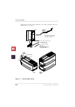
Page 243: ...an example of how a typical ACD call is handled The Strata CT System provides many ACD functions and custom keys on for Toshiba DKT2500 series telephones For instance the ACD Supervisor can monitor calls and assist Agents through use of an LCD telephone programmed especially for the Supervisor which shows ACD Agent and Group information Telephone instructions are provided in the Strata CT ACD Supe...

Page 244: ...erface options SMDR page outputs SMDR relay controls alarm sensor and door lock functions on PIOU or PIOUS will be active on the installed PIOU PIOUS that is programmed with the lowest Program 03 code 41 42 or 43 Code 41 Enables Remote Maintenance Code 42 Enables MIS SMIS PIOU or PIOUS Slot The TTY port must have Code 42 set for its slot in Program 03 to support ACD MIS Code 43 Enables RS 232 Voic...

Page 245: ...ces to standard telephone PCB ports RSTU and PSTU Digital announcement devices and music sources can be assigned to any standard telephone port they are not restricted to designated Background Music BGM source ports see Program 14 3 for assignments Announcement devices are designed to connect directly to standard telephone ports Do not use an isolation transformer to connect digital announcers Imp...

Page 246: ...nitialise the processor PCB when installing the ACD feature unless the processor PCB ROMs or flash memory are changed to install ACD If changing ROMs DK Admin or DK Backup software is recommended for downloading uploading previously programmed customer data Step 2 Install the Feature Key To install the RKYS onto the Processor PCB Read the section titled RKYS Feature Key Upgrades on Page 2 38 for i...

Page 247: ... the Agent s PhDN SMIS registers ACD and PBX calls An ACD call is a call that is sent directly or transferred to the ACD group A PBX call is a call that is sent to the Agent s ACD Call button PhDN or a call originated from an Agent s ACD Call button PhDN Based on a total system speed of 10 800 bps 9600 1200 for auxiliary serial channels and a requirement of one channel each for SMDI TTY SMDR and M...

Page 248: ...m 14 3 Code 4 Music source timers are set in Program 11 5 1 2 and 3 Step 9 Install ACD to Strata CT Built in Auto Attendant AA Integration If ACD calls route to an ACD Group via the Strata CT built in AA install and program the AA per Strata CT Built In Auto Attendant AA on Page 6 46 Auto Attendant single digits are assigned to ACD Groups in Program 09 Step 10 Assign ACD to Toshiba Stratagy or Cus...

Page 249: ...ACD Groups If a loop start line is assigned to an ACD Group in Program 14 0 it routes per that ACD Group s call routing assignments ACD calls ring on Agent ACD Call PhDN buttons Do not assign Exchange Line or Pooled Line Grp buttons to Agent telephones ACD Exchange Line or Pooled Line Grp buttons can be assigned to overflow destination telephones Note Program 14 0 has priority over all other ringi...

Page 250: ...e Calls Calls can be assigned to ring external AA ports in Program 81 89 The external AA can be programmed to transfer calls to particular ACD Groups by assigning one digit dialling prompts to each Group DDI Line Calls Calls can be assigned to ring directly into an external AA by assigning incoming digits to the AA ports in Programs 81 83 Internal station to station DN calls cannot be transferred ...

Page 251: ...ing or built in AA DDI Tie lines route to the substitute destination DN assigned in Program 14 2 This applies to overflow queue time out and overflow point destinations assigned in Programs 14 4 11 1 and 14 5 respectively If the overflow destination DN is busy when overflow time occurs the ACD call does not overflow but remains in the ACD queue until the overflow destination DN or an Agent telepho...

Page 252: ...n the After Shift mode If the All Agents Unavailable Operation is set to route calls to the Overflow Point destination set in Program 14 5 Program 10 4 LED 04 On calls to a Group whose Agents are all unavailable are treated as if they overflowed from the Group s queue even if the overflow destination is busy If the All Agents Unavailable overflow destination is another ACD Group calls route to an ...

Page 253: ...estination is the CT attendant console RNA calls ring or queue on the console whether it is busy or idle This applies to loop Tie or DDI lines ACD SMDR Printout Examples Auto Attendant DDI and Tie line ACD calls can be identified on SMDR printouts Several SMDR printout examples noting ACD information are provided See Figures 7 3 through 7 10 However Toshiba recommends using Insight DK to track ACD...

Page 254: ... 00 01 23 Queue Ring Agent Time Time Agent answers call Ring Time before First Announcement Answers Duration Program 11 4 4 seconds Time call is disconnected Agent Primary Directory Number PDN Agent Talk Time Duration ACD Call goes to Queue then rings Agent Agent Answers Agent Telephone PDN Exchange Line Number 00 05 02 38 01 23 03 66 Total time call is connected to system is 4 minutes 6 seconds 2...

Page 255: ...connected to Line 007 Line Number Note DISA callers cannot dial into an ACD Group Identifies DISA or Built in AA call 2080 003 203 13 10 00 00 10 00 03 ACD 003 ACD 204 13 10 00 00 06 204 003 204 13 10 00 00 26 203 Ring before Answer Time Duration 203 Transfer Time 203 Talk Time Duration Indicates Call Transfer to ACD Group 204 Talk Time PDN of telephone that answers the ACD transferred call 204 Ri...

Page 256: ...Lost or Abandoned Calls DDI Caller ID Number Storage Direct ACD call does not go to queue but rings Agent Abandoned call is stored on Agent telephone Direct ACD call does not go to queue but rings Agent Agent does not answer and call goes to Ring No Answer RNA destination telephone Abandoned call DDI Caller ID Number is stored on RNA destination telephone Direct ACD call rings to ACD Group Caller ...

Page 257: ...rd in order for the Insight CT to work Reference Information For refernce information refer to the Insight DK Installtaion Programming Guide for software installation and operating instructions Wall boards Insight DK ver 3 0 supports the following wallboards Line Driver An RS 232 short haul modem or Line Driver is needed to boost transmission for PCs located more than 21 metres from the Strata CT ...

Page 258: ...ACD Installation 7 16 Strata CT I M Manual October 2000 H C ...
Page 259: ...me that the fault was discovered and reported by a digital or electronic telephone user All faults therefore are classified according to the way they would appear at the digital or electronic telephone Fault Clearing Procedures Before attempting to clear any fault ensure that it is in the system and not caused by associated external equipment such as wiring MOH source etc Important Many system fea...

Page 260: ... grounded cabinet Touch the PCB contacts with your fingers Important If the fault is not cleared by substituting a PCB reinstall the original PCB in the KSU cabinet before trying another PCB Parts Return 1 Pack the part in a suitable container original box is highly recommended Use anti static containers for all PCBs and feature cartridges Use plastic bags for digital or electronic telephones KSU ...

Page 261: ...on 3 If there are feature keys verify that they are correctly installed Strata CT verify correct installation of the BRCS or RKYS options on the processor PCB per the Installation chapter 4 For the Strata CT make sure the system power is Off Then install an processor PCB in the appropriate slot of the Base Cabinet Strata CT If B2CBU B3CBU or B5CBU is installed install its partner card B2CAU or B3C...

Page 262: ...le 8 2 for electronic telephone ports The reading will be a plus or minus depending on meter lead placement 4 An improper reading indicates an open crossed or shorted wire See Power Supply BPSU672F Removal on Page 2 8 and Power Supply Replacement on Page 2 8 5 For the MDF to telephone digital or electronic cable use an ohmmeter to make a more precise check Table 8 1 Station Cable Continuity Check ...

Page 263: ...DSSs DDCBs and Table 8 4 for electronic telephones and HDSSs 5 An improper reading indicates an open crossed or shorted wire See Power Supply BPSU672F Removal on Page 2 8 and Power Supply Replacement on Page 2 8 Table 8 2 Station Cable Continuity Check for Electronic Telephone Cables using Voltmeter From To Voltage Pair Wire Colour Pair Wire Colour 1 T Green1 1 The green red black yellow and white...

Page 264: ...short or long of cable bridge Test for and eliminate all cable bridges 3 When installing the station cable do not run parallel to and within 3 ft of an AC power line AC power lines should cross at right 90 angles only In particular avoid running station wire pairs near devices that generate electrical noise such as neon or fluorescent light fixtures Table 8 3 Station Cable Continuity Check for Dig...

Page 265: ... green red black yellow and white blue measurements should be within 10 of each other 2 T Black open 1 R Red 2 T Black open 1 T Green 2 R Yellow open 1 R Red 2 R Yellow open 1 T Green 1 R Red 40 ohms2 2 This is the maximum allowable reading for all digital and electronic telephone cable runs except if connecting an HDSS console to circuits 7 and 8 of a PEKU then the maximum cable restriction is 20...

Page 266: ...fault Is a DSS console non operational Is it a voice mail auto attd fault Is it an SMDR fault 1 1 Call your technical support group No No No No No Is it a remote maintenance fault Is the fault classified on this page No No 1 1 No Yes Yes Yes Yes Yes Yes Yes Yes 1879 CT I M Go to Flowchart 8 2 Go to Flowchart 8 8 Go to appropriate Flowchart 8 1 8 8 Go to Flowchart 8 3 Go to Flowchart 8 4 Go to Flow...

Page 267: ...after entering customer database Reprogram customer database one program at a time and check to see if fault re occurs Tag the defective unit s and return for repair 2 1 2 2 2 5 2 6 2 8 2 3 Go to Flowchart 8 1 2 4 2 7 END END No Yes Yes No No Yes Yes No Test the Power Supply as described in the Installation Chapter Also perform Hardware Fault Isolation per this chapter 1880 CT I M Re initialise th...

Page 268: ...aulty station s only in the Expansion cabinet Is the fault cleared 3 7 No Retest 3 5 YES Is the fault cleared Yes 3 6 END Go to 3 4 Go to 3 4 Call your technical support group No Yes No No No 3 8 Yes Is the fault cleared No Yes 3 4 Replace the defective unit and return it to the repair center Strata CT PEKU PESU PSTU RSTU RDSU RSTS Replaceable Station PCBs Check station wiring per the Station Cabl...

Page 269: ...d Go to 4 5 4 7 No No Are the faulty Exchange lines only in the Base or Expansion Cabinet 4 10 4 5 Is the fault cleared 4 4 Yes START Is the fault cleared 4 1 4 2 END No Locate the faulty Exchange lines Yes Change the PCB and retest 4 3 Yes 1 2 No Replace the defective unit and return it to the repair center END 4 9 Yes Change the expansion unit and retest 4 6 1882 CT I M Check Exchange line wirin...

Page 270: ... Refer to Chapters 4 and verify wiring Is the fault cleared Yes 5 4 Go to 5 3 HDSS No On PEKU connected to HDSS set SW1 to the DSS position 5 1 No 5 2 Is the fault cleared For DDSS circuit 8 of the base unit or PDKU For HDSS circuit 7 and 8 of PEKU PESU does not support HDSS Correct as necessary Correct as necessary Is the fault cleared Yes 5 5 Call your technical support group No END END No Yes Y...

Page 271: ...s 656 and 657 are stored correctly in users digital or electronic telephones Use operating procedures in the manual for instructions 6 1 Check that the BRCS is installed correctly and programmed with Code 92 93 94 in Prog 03 No Check that VM AA ports are connected to standard telephone station ports correctly Refer to KSTU2 RSTU3 PSTU PESU wiring diagrams in Chapter 4 Correct if necessary Is the f...

Page 272: ...uctions in Chapter 4 Fix as required Is the fault cleared Yes 7 8 No END Is the fault cleared Yes 7 9 No END Call your technical support group No No other faults are classified Call your technical support group for assistance No The SMDR port is the bottom modular jack TTY is on top of PIOU PIOUS SMDR can be any jack on RSIU or RSIS See Program 76 1 2 The modular cord connecting to the SMDR port m...

Page 273: ...connecting the TTY port to the terminal or external modem must be 6 wires TTY can be any jack on RSIU RSIS see Progam 76 Check that the baud rate switch SW2 push button switch on PIOU PIOUS is set to match the remote terminal baud rate 300 bps LED ON 1200 bps LED OFF Check that the RSIU RMDS IMDU RSSU PIOU or PIOUS is installed correctly If using RSIU RSIS RMDS check that Program 76 settings match...

Page 274: ...Fault Finding 8 16 Strata CT I M Manual October 2000 H C ...
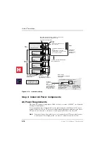
Page 275: ...0 series telephone Installation instructions for the hardware are contained in the Strata DK280 I M July 1996 Manual Chapter 6 paragraph 9 Windows Telephony is a component of Windows Open Services Architecture This architecture provides telephony services when connected to many different telephone switches Therefore an application needs to know only the definition of the API Application Program In...

Page 276: ...l TAPI as part of the normal installation process Note Toshiba currently do not support the Installation of StrataLink or the Toshiba Driver on NT4 Server StrataLink and TAPI Service Provider for Windows 95 NT Step 1 Remove Previously installed DKT TAPI Service Provider Applications 1 Click on the Start Button Settings then Control Panel Figure 9 1 Start Bar 2 Click on the Start Button Settings th...

Page 277: ...Computer Telephony Integration Strata CT I M Manual October 2000 9 3 Figure 9 2 Control Panel Figure 9 3 Selecting the Toshiba Driver H C ...

Page 278: ...re 9 4 Installing StrataLink and Telephony Driver 3 When the Package Selection menu appears select the appropriate option to install either software package or both software packages recommended Figure 9 5 Selecting Install Options 4 When the Automatic Start up menu appears make sure that Add StrataLink to the Start up Group is checked 5 Follow the remaining Installation Wizard instructions to com...

Page 279: ...To initialise StrataLink and TAPI Service Provider 1 Press the Windows Start button select Programs StrataLink 2 Click Enable TAPI Figure 9 7 StrataLink Main Screen The light above this box will be red at first then yellow as the TAPI Service Provider is initialised and finally green when initialisation is complete Press Driver Set up to configure the TAPI Service Provider H C ...

Page 280: ...igure 9 8 Configuring the Toshiba Driver 6 Select phone type 10 or 20 key 7 Select the switch type from the drop down menu 8 Disable Reverse Screen Pop to turn soft keys on Enable to turn soft keys off Note Current UK software will only support 3 or 4 digit extension numbers 9 Select a button 10 Choose a function from the list Figure 9 9 Configuring the driver to match the keyset programming 11 Na...

Page 281: ...On NT Windows 2000 1 Telephony Services must be running for TAPI and StrataLink to work This can be checked by double clicking on the Services icon in Control Panel 1a Choose the Telephony services from the list box The Startup column should be set to Automatic to allow Windows NT to automatically start Telephony Services when an Application like StrataLink attempts to use Telephony 1b To change t...

Page 282: ...omponent resides between the Telephony API called by applications and the Telephony SPI implemented for the specific switch to which the PC is connected The software applications call TAPI functions that are managed by TAPI DLL and routed to the Service Provider interface e g Toshiba s DKT SPI for execution The relationship between these components is shown in Figure 9 10 Figure 9 10 The Telephony...

Page 283: ...rpretations of them The application therefore is responsible for the complete interaction of the feature or service provided Interfaces The Windows Open System Architecture provides two interfaces for Telephony Devices The TAPI interface provides for the control of calls using a well defined interface and the audio connection is handled in what Microsoft calls a Media Stream To allow for a standar...

Page 284: ... the two mechanisms are used together as when application receives a LINE_CALLSTATE message after which it checks the information contained in the LINECALLINFO structure by calling lineGetCallInfo Strata DKT TSPI supports the following messages providing unsolicited information LINE_CALL STATE Sent to an application to notify it about changes in a call s state LINE_LINEDEVSTATE Sent to the applica...

Page 285: ...gotiate the API version number to be used The application provides the range of versions it is compatible with and TAPI DLL in turn negotiates with the TSPI to determine which version range it supports LineOpen This function opens the specified device ID for the purpose of monitoring or control by the application Opening the line returns the handle for the device The application can then use this ...

Page 286: ... TSPI dwPermanentLineID This field will contain the permanent device ID as found in TELEPHON INI dwLineNameSize dwLineNameOffset This memory area contains the name of the device as defined in Set up of the driver installed dwStringFormat STRINGFORMAT_ASCH dwAddressModes LINEADDRESSMODE_ADDRESSID dwNumAddresses This field reports the number of addresses found for this device This is defined in Set ...

Page 287: ... LINEDEVSTATE_CONNECTED LINEDEVSTATE_DISCONNECTED LINEDEVSTATE_OPEN LINEDEVSTATE_CLOSE LINEDEVSTATE_NUMCALLS LINEDEVSTATE_REINIT LINEDEVSTATE_TRANSLATECHANGE dwUUIAcceptSize dwUUIAnswerSize dwUUIMakeCallSize dwUUIDropSize dwUUISendUserUserInfoSize dwUUICallInfoSize Not supported by Toshiba DKT TSPI MinDialParams MaxDialParams DefaultDialParams These will indicate the dial speed duration and dial p...

Page 288: ...RWARD PDN or INT only dwCallInfoStates LINECALLINFOSTATE_OTHER LINECALLINFOSTATE_APPSPECIFIC LINECALLINFOSTATE_NUMOWNERINCR LINECALLINFOSTATE_NUMOWNERDECR LINECALLINFOSTATE_NUMMONITORS LINECALLINFOSTATE_DIALPARAMS dwCallerIDFlags LINECALLPARTYID_UNAVAIL dwCalledIDFlags LINECALLPARTYID_UNAVAIL dwConnectedIDFlags LINECALLPARTYID_UNAVAIL dwRedirectionIDFlags LINECALLPARTYID_UNAVAIL dwRedirectingIDFla...

Page 289: ...S_PICKUPCALLWAIT dwCallFeatures LINECALLFEATURE_ADDTOCONF LINECALLFEATURE_ANSWER LINECALLFEATURE_BLINDTRANSFER R3 only LINECALLFEATURE_COMPLETETRANSF LINECALLFEATURE_DIAL LINECALLFEATURE_DROP LINECALLFEATURE_HOLD LINECALLFEATURE_PARK LINECALLFEATURE_PREPARETOADDCONF LINECALLFEATURE_SETUPCONF LINECALLFEATURE_SETUPTRANSFER LINECALLFEATURE_UNHOLD dwRemoveFromConfCaps LINERMOVEFROMCONF_NONE dwRemoveFr...

Page 290: ... Not supported by Toshiba DKT TSPI Field Name Setting dwNumInUse 1 if there is a call associated with the address 0 otherwise dwNumActiveCalls 1 if there is a call in any state other than ONHOLD at the address 0 otherwise dwNumOnHoldCalls 1 if there is a call holding at the address 0 otherwise dwNumOnHoldPendingCalls 1 if there is a call in either the ONHOLDPENDINGCONF state or the ONHOLDTENDTRANS...

Page 291: ...ffffffff Unknown dwCallerIDFlags dwCallerIDSize dwCallerIDOffset Provides Caller ID number when provided by the public network Internal calls give caller ID number if LCD Name is off and Caller ID name if the LCD name feature is on dwCalledIDFlags dwCalledIDSize dwCalledIDOffset The DDI number received or Strata CT alphanumeric tag are provided dwConnectedIDFlags Not supported by Toshiba DKT TSPI ...

Page 292: ...e dwCalledPartyOffset Not supported by Toshiba DKT TSPI dwCommentSize dwCommentOffset dwDisplaySize dwDisplayOffset If the call being referenced is the active call on the line these fields will contain the contents of the two line LCD display currently being shown dwUserUserInfoSize dwUserUserInfoOffset Not supported by Toshiba DKT TSPI dwHighLevelCompSize dwHighLevelCompOffset Not supported by To...

Page 293: ... dwStringFormat STRINGFORMAT_BINARY dwStringSize dwStringOffset 4 A DWORD containing the ID for the line device specified Field Name Setting dwNumOpens The number of instances this application opened normally 1 dwOpenMediaModes LINEMEDIAMODE_INTERACTIVEVOICE dwNumActiveCalls The number of calls ringing and or connected dwNumOnHoldCalls The number of calls that are on hold dwNumOnHoldPendCalls The ...

Page 294: ...e line will transition to the LINECALLSTATE_DIALTONE state The lineDial function can be used at this point to dial the destination address LINECALLPARAM default Field Name Setting dwBearerMode LINEBEARERMODE_VOICE dwMinRate dwMaxRate 0 3 1kHz 0 dwMediaMode LINEMEDIAMODE_INTERACTIVEVOICE dwCallParamFlags 0 dwAddressMode LINEADDRESSMODE_ADDRESSID dwAddressID anyavailable DialParams 0 0 0 0 dwOrigAdd...

Page 295: ... answered or placed on hold by a TAPI application LineDeallocateCall This function releases resources used to keep track of a given call This function can only be called while the state is idle Holding Calls lineHold This function places the specified call on hard hold This can be used when in either LINECALLSTATE_CONNECTED or LINE CALLSTATE_PROCEEDING states The application can place a call on ho...

Page 296: ...es a conference call connects the original call to the conference and allocates a consultation call whose handle is returned to the application The application can then use lineDial on the consultation call to establish a connection to the next party to be added lineDrop can be used to abandon this call attempt The third party is added with the function lineAddToConference which specifies both the...

Page 297: ...logue for the DKT TSPI device The configurable options are the minimum number of digits necessary for an outside number and the access code that should be used to obtain an outside line These two parameters are used when a complete destination address is supplied with lineMakeCall to determine whether the destination is internal or external Any changes made will take place immediately the service ...

Page 298: ... OFF until the call is answered The LCD and LED events are available to applications who negotiate with the service provider for extension version 1 0 lineNegotiateExtVersion After successfully negotiating this version the service provider will send the LINE_LINEDEVSTATE notification message with the dwParam1 set to LINEDEVSTATE_DEVSPECIFIC each time the information changes To retrieve this snapsh...

Page 299: ...peed_Dial ESpeed_Dial_Pause EData EData_Release typedef struct_tagFLEXKEY Current LED Flash Rate EledFlashRate eFlashRate Current LED Colour ELedColour eColour Key Type EKeyType eType Label assigned to key char szLabel MAX_LABEL 1 FLEXKEY PFLEXKEY typedef struct_tagDKTSNAPSHOT 10 or 20 button int nNumKeys Flex Key Array FLEXKEY FlexKeys MAX_KEYS Speaker LED Status Colour Red or off EledFlashRate e...

Page 300: ...on Single Action Keys Single Action Keys Dual Action Keys Key Name Code Key Name Code Key Name ON OFF Flex Key 01 05 Digit 1 24 Hook Switch 07 15 Flex Key 02 13 Digit 2 32 Mic 45 48 Flex Key 03 21 Digit 3 40 Spkr 44 46 Flex Key 04 29 Digit 4 25 Conf Trns 22 23 Flex Key 05 37 Digit 5 33 Vol Up 28 50 Flex Key 06 00 Digit 6 41 Vol Dn 36 38 Flex Key 07 01 Digit 7 26 Scroll 47 49 Flex Key 08 02 Digit 8...

Page 301: ...mation Systems but we are willing to help by talking to systems integrators to assist where possible StrataLink will work with Toshiba s V2 36 TSPI or above Both will be packaged together and will ship with each PCIU The installation procedure will provide options for installing the TSPI StrataLink or both StrataLink communicates with these software applications using Microsoft Windows Open System...

Page 302: ...r this operation Test Debugs and Monitors StrataLink provides several important testing and debugging functions These tools enable the installer to verify whether the link is functional and by using the TAPI link to view the details of the information being passed Without these tools the troubleshooting or verifying operation is reduced to guessing Software Application Initiated Events Dialling Pr...

Page 303: ...ds to StrataLink Some application programs for example GoldMine must be configured to use these DDE commands StrataLink wherever necessary offers more than one format for each command See your program s Application Notes for applicable commands The following are some examples Figure 9 13 Dialling preference Screen Dial Dial a telephone number on the specified line appearance If the line appearance...

Page 304: ...riggering event can be any number of things e g Call Ringing Call Connected or Call Cleared The existing Trigger Rules can be displayed Figure 9 14 edited deleted or new rules added to meet the needs of the application These functions are important when setting up the desktop PC Multiple rules can be created at the same time Figure 9 14 Trigger Rules Screen Add Change a Trigger Rule When adding or...

Page 305: ... used on any line or a specific line If the same Trigger applies to some lines but not to others the rule must be entered for each line to which the rule applies Conditions Conditions i e Phone State include performing the action if not talking or trunk number is available You may not want to have an Action performed while you are talking on a call Again the most common example is Screen Pop where...

Page 306: ...igure 9 17 Add Edit Actions Screen Action Name Every event Action has a Name which you should set to describe the result the Action is trying to cause like Beep My Pager This name is used in the Trigger Rules Type Select from the pull down menu the type of Action to be performed Each Action has one or more parameters that must be provided by the user installer These parameters often contain tokens...

Page 307: ...luded in the command string Show Test Params Button When you set up an Action it is always a good idea to make sure the Action works correctly The Test button will pop up a Test Action screen for this purpose Using this screen you can simulate parameters e g Calling Phone Number and Calling Name and press the Test button to execute the Action with the test parameters Parameters can be changed for ...

Page 308: ...rch String P Beep My Pager Golden Page software from Golden Gate Software While the telephone is ringing this Action displays a message with the caller s Caller ID on a pager so that the person can decide whether to pickup the call Action Type DDE Execute App Name SENDPAGE App Topic SYSTEM DDE Executive String PAGE MYPAGER Call From H N 1 Pop Day Timer Organizer Screen pop Day Timer Organizer Day ...

Page 309: ...n function For Screen Pop to work the appropriate Trigger Rules must be set up Figure 9 18 TeleMagic Link Menu Pop TeleMagic Sends a Pop or LookUp command to TeleMagic with the configuration you specify This is used to Screen Pop the TeleMagic contact manager when a call rings in Pop TeleMagic parameters are Index Level Tells TeleMagic the level on which to perform the search e g 1 2 3 etc Leaving...

Page 310: ...n should be programmed properly as they will be interrogated and used as the Appearances by StrataLink Whenever you make configuration changes to the TAPI Service Provider it is recommended that you exit and restart StrataLink Figure 9 19 TAPI Test Screen Debugging Provides two tools for monitoring communication activity to and from StrataLink This is especially useful when you are setting up and ...

Page 311: ...m This application s bulletin provides ideas for linking Goldmine 95 to the Strata CT system but always consult your Goldmine manuals when customising Goldmine for your application This bulletin only supplies ideas and set up parameters to create an interface for linking the telephone network information with the Goldmine database For more in depth information on the features capabilities and sett...

Page 312: ...provide a full desktop dialling and screen pop interface between the Toshiba StrataLink and Goldmine 95 In the directory where Goldmine is installed default is C Goldmine add the following two lines with a text editor or word processor to each of the INI files The INI files are named after each user For example user Jerry would have a USER INI file named JERRY INI Modem DDEDial Dial STRATLNK Dial ...

Page 313: ... new actions make sure that you fully understand GoldMine s DDE capabilities because they are made at your own risk Toshiba Technical Support only supports the predefined actions Figure 9 23 POP action for Goldmine The DDE execute string CALLERID P N 2 can be changed to control how the screens work in Goldmine when a call arrives The most common option in the third parameter is defined as 0 in the...

Page 314: ...s Figure 9 24 Trigger Rules for Goldmine The two Trigger Rules shown above enable a screen pop for two situations when a call arrives and the user is not busy on another call Call Ringing and when a call is connected Call Connected The user can handle multiple calls If your first call is placed on hold the second call is identified You can chose to return to the first held call or to answer the se...

Page 315: ...or less digits This could create a problem if other programs such as a fax application use the same setting In this case the area code would have to be entered correctly Create additional prefixes and suffixes to customise the dialling of your number by using the PREDIAL INI file in Goldmine Details can be found in the Goldmine Reference Manual under Customising Goldmine Create a plan to dial all ...

Page 316: ...ature Defining a tool bar icon Right click on an empty space on any tool bar and a pop up menu is displayed From the pop up menu select Record Macro Click on the File Menu then select Hang up Answer or ACD Calls Click the Stop Recording macro button square icon and place the icon on a tool bar Repeat the steps for each icon to be defined Placing icons on the tool bar Right click on any blank space...

Page 317: ...lication This bulletin only supplies ideas and set up parameters to create an interface for linking the telephone network information with the ACT database For more in depth information on the features capabilities and settings for ACT you should consult the supplier or manufacturer of the software Linking ACT 3 0 with StrataLink Act 3 0 contact management software package in conjunction with the ...

Page 318: ...ERYONE must be selected to handle multiple calls ACT treats all line buttons equally ACT does not provide information on held calls it only provides automatic screen pops for Call Ringing events StrataLink addresses many of these issues and provides capabilities to flexibly control these events Installing ACT 3 0 Step 1 Install the Toshiba StrataLink TAPI Service Provider Insert the first diskette...

Page 319: ...lly cleared set the timer to automatically start a timer for calls set a preference for outbound line button selection Figure 9 29 ACT Preference Screen Step 4 Open Strata Link StrataLink needs to be initialised for controlling ACT for incoming calls This is done by creating a set of Trigger Rules for operation The following rules are a guide for creating a set of rules that will work for your app...

Page 320: ...st be within this group To automatically search all records to allow a call to be placed on Hold and move to a second or third caller the search should be opened to all records in the file CAUTION Use caution when employing Call Hold and Call Clearing trigger rules If multiple phones have the same line appearances calls placed on hold and disconnected from each one of the other phones will trigger...

Page 321: ...ss exposed object model and the Jet Data Access Object DAO and is beyond the scope of this document This application s bulletin provides ideas for linking Access 97 to the Strata CT system but always consult your Access manuals when customising Access for your application This bulletin only supplies ideas and set up parameters to create an interface for linking the telephone network information wi...

Page 322: ... Dial action An example of how to do this is below On Error GoTo Err_StrataLinkdial lngStrataLinkChannel Application DDEInitiate stratlnk System On Error GoTo 0 Application DDEExecute lngStrataLinkChannel Dial strtodial Application DDETerminate lngStrataLinkChannel Err_StrataLinkdial Exit Sub Handling Incoming Calls Simple Cases For simple applications the DDE command itself can be used to perform...

Page 323: ...e the hidden form will close itself after it has dealt with the DDE request Private Sub Form_Open Cancel As Integer Deal with the ringing request Get the arguements supplied by StrataLink Dim strArgs As String If IsNull Me OpenArgs Then Cancel True Exit Sub End If strArgs Me OpenArgs Parse the arguments and remove quote marks intLine GetLineFromArgs strArgs strCallingParty Trim GetCallingPartyFrom...

Page 324: ...ls when customising Outlook for your application This bulletin only supplies ideas and set up parameters to create an interface for linking the telephone network information with the Outline database For more in depth information on the features capabilities and settings for Outlook you should consult the supplier or manufacturer of the software Handling Outgoing Calls Telephone Number Format Outl...

Page 325: ...rosoft Outlook Active X object hierarchy Toshiba Information Systems UK Ltd can supply the Tlink for this purpose Dealing with Incoming CLI The incoming CLI must be mapped from the StrataLink TSPI format to the format Outlook uses See Telephone Number Format on Page 9 50 There are two forms of CLI that StrataLink TSPI uses There is a CLI format for national numbers and a format for international n...

Page 326: ...Computer Telephony Integration Handling Incoming Calls 9 52 Strata CT I M Manual October 2000 H C ...
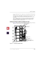
Page 327: ...l adapters Each device can support voice and or RS 232 switched circuit data The station side BRI S T circuits are point to multipoint A subassembly RBSS can be attached to the RBSU for two additional BRIs for NT type station side connections only The RBSU PCB and the RBSS subassembly are shown in Figure 10 7 on Page 10 12 and Figure 10 8 on Page 10 13 respectively The combination of RBSU and RBSS...

Page 328: ...System Capacity of ISDN Circuits The capacities of ISDN lines and stations for all CT systems are shown in Table 10 1 Table 10 1 Maximum Number of RPTU PCBs Lines Processor Max PCBs Max B Channels Lines B1CAU 2 32 B2CAU BU B3CAU BU 4 120 B5CAU BU 7 200 H C ...

Page 329: ... to synchronise the RPTU PCB and the CT time switch to the public switched telephone network One RPTU or RBSU must extract the clock from the ISDN provider The selected unit is designated as the Primary timing source in system Program 42 1 In remote cabinet applications the Primary clock source PCB must be installed in the Base Cabinet main location For more information refer to Timing and Synchro...

Page 330: ...gnments on Strata CT Slot Assignments on Page 10 3 and apply firm even pressure to ensure proper seating of connectors 3 After installing the RPTU gently pull the PCB outward If the connectors are properly seated a slight resistance is felt PRI Lines Needed Slots Needed RPTU PCBs Needed1 1 RPTU PCBs do not have to be installed in the order shown in this table Example If only one RPTU is needed it ...

Page 331: ...matically revert to the Secondary Clock source PCB Program 42 2 and Program 42 1 will have to be reprogrammed Resets or initialises the RPTU firmware Press this switch to correct an out of service condition or just prior to connecting to the Network PRI J1 8 pin Modular Connector RJ45 Connects the RPTU to the PRI ISDN line J2 6 pin Modular Connector RJ11 Connects the RPTU to a terminal or PC to mo...

Page 332: ...xchange Off Circuit is working properly LOS Loss of Signal On I C signal cannot be detected Off Circuit is working properly RST Reset On CPU is resetting the software Off Circuit is working properly BSY Busy On One or more B channels are busy Off All B channels are idle TS Timing Signal On Circuit is secondary timing source Off Circuit is not used for system timing Flashing Circuit is primary timi...

Page 333: ...oops connect only the RPTU end of the shielded cable to earth The NTE earth should not be connected to the cable shield A detailed pinout diagram for the RJ45 jacks and the modular cords adaptors is shown in Figure 10 3 on Page 10 7 Toshiba will ship a 5 metre shielded patch cord terminated with BS EN28877 connectors with each RPTUIF Cable Installation The RPTU PCB is shipped with a Toshiba RPRI c...

Page 334: ...connecting to ISDN station equipment Older Version s none The Strata CT system supports the RBSU RBSS interface unit according to the common control unit resident in the system refere to Table 10 1 RBSU RBSS switches jumpers and connectors are shown in Figure 10 7 on Page 10 12 and Figure 10 8 on Page 10 13 and described in Table 10 5 LEDs on the RBSU RBSS show a continuous status of BRI operation...

Page 335: ...o line numbers and two station port when configured as line side or station side on the RBSU Circuits installed on the RBSS use only station ports The RBSU connection options BRI line or ISDN TE 1 TA devices are selected in Strata CT customer database programming and option switches located on the RBSU The RBSU circuits that connect to the ISDN network side requires a NT1 interface box to convert ...

Page 336: ... RBSS PCBs can be installed in any combination so long as the number of RBSU PCBs is the same or greater than the number of RBSS PCBs PS 1 Line Power Option The RBSU provides an optional line power supply R40S1A that will supply line power to TE devices This power option only applies to RBSU or RBSS circuits that are configured in the NT mode See Figure 10 10 to install the R40S1A Each of the four...

Page 337: ...y 3031 RX TX Pin 3 Pin 6 Pin 4 Pin 5 Pin 3 Pin 6 Pin 4 Pin 5 RX TX TE Device Power sink R40S PS 1 Power Source RJ 45 Pin Nos on RBSU or RBSS NT circuit RJ 45 Pin Nos on TE device R40S Power Limits Voltage 33 3 VDC to 38 85 VDC maximum Current 100mA maximum 25mA maximum per each RBSU RBSS circuit TE RBSU H C ...

Page 338: ...he Strata CT Programming Manual under the ISDN tab Step 2 Set Option Switches Jumpers Set all option switches and jumpers on theRBSU and RBSS PCBs before plugging the RBSS onto the RBSU or inserting the RBSU into the system RBSU RBSS switch jumper information and locations are shown in Figures 10 7 10 8 and Table 10 5 Figure 10 7 RBSU PCB RBSU1A CM V 1 RBSU1 2789 RBSU1A BSY TS LOS FS BSY TS LOS FS...

Page 339: ...m resistor in out of the circuit 1 SW 4 5 Jumper N A On Switches PS 1 in out of the circuit 2 SW 6 Jumper X X Causes the circuit to operate as TE or NT1 2 SW 7 Slide On Off Switches a 100 ohm resistor in out of the circuit 2 SW 8 9 Jumper N A On Switches PS 1 in out of the circuit RBSS 3 NT only SW 1 Slide On Off Switches a 100 ohm resistor in out of the circuit 3 NT only SW 3 4 Jumper N A On Swit...

Page 340: ...ile observing the UP arrows on the R40S1A 2 Plug the R40S1A onto the RBSU Figure 10 9 Location of RBSU Plug on PCBs Step 5 Install RBSU RBSS PCBs into Cabinet After setting the switches and jumpers and installing the plug on PCBs as described in the preceding paragraphs the RBSU RBSS PCBs can be installed in the appropriate cabinet slots After the RBSU RBSS is installed in the Strata CT cabinet th...

Page 341: ...ED Indication BSY Circuit Busy On Either B channel is in use Off B channels are idle TS Timing Source Blinking On Off The RBSU is extracting the clock from the BRI line and is the Primary synchronisation circuit for ISDN On The RBSU is the secondary backup synchronisation circuit for the ISDN Off The RBSU is not used for ISDN or T1 synchronisation LOS Loss of Signal On Clock timing cannot be detec...

Page 342: ...tic Compatibility EMC requirements As of Release 4 1 RBSU complies with EMC requirements without earthing TB3 on the RBSU so it is not necessary to connect an earth wire to TB3 BRI Wire Type Recommendations CAT5 wire is recommended for ISDN BRI customer premises wiring While the ISDN BRI signal works for some distance over almost any wire that is suitable for analog voice service better wire enabl...

Page 343: ...wisted cable with an RJ modular plug at both ends will have the locking tab of the plug on one end up and on the other end down as shown in Figure 10 11 A cord of up to 10 meters connects the ISDN BRI RJ45 wall jack to the desktop TE Figure 10 11 Modular ISDN Data Cable RBSU Reset Switch resets RBSU Firmware RS232C Connector for Call Data Monitor RJ45 8 pin shielded Modular Connector BSY TS LOS FS...

Page 344: ...e U interface to the RBSU BRI four wire T interface The connection between the NT1 and the RBSU TE circuit is a point to point connection so the NT1 can connect to only one RBSU BRI TE circuit A 100 ohm Terminating Resistor TR is required on each end of the point to point connection The TR must be switched into the RBSU TE circuit refer to option switches in Table 10 5 on Page 10 13 and off at the...

Page 345: ...ting interfaces R reference point to the ISDN S T protocol TA devices include asynchronous circuit switched adapters that convert RS 232 async data like data from a PC COM port to B channel 64 kbps sync TAs also enable you to connect standard telephones and non ISDN fax machines to receive and make calls over ISDN circuits TEs include any user device telephone fax PC video conference board that is...

Page 346: ...a TR on the RBSU RBSS NT circuit side and not on the TE or TA device side of the bus The RBSU and RBSS circuits provide an option switch that allows the 100 ohm TR to be switched into the circuit on the CT side of the bus see Table 10 5 on Page 10 13 Most TE 1 and TA devices also provide option switches to connect 100 ohm terminating resistors as shown in Figure 10 12 If the TE or TA devices do no...

Page 347: ...p of RBSU Unit Socket with terminating resistor CT I M fig 15 100m CW1308 150m CW 1700 or 1750 Wiring Short Passive Bus Maximum number of sockets 12 Maximum number of terminals connected 8 Pin number 1 Pin number 8 Grey RJ45 socket Top of RBSU Unit Socket with terminating resistor CT I M fig 16 250m CW1308 400m CW 1700 or 1750 Wiring Extended Passive Bus Maximum number of sockets 12 Maximum number...

Page 348: ... clock provider If the PRI and BRI are not synchronised to the same clock provider the Strata CT could experience slip problems Timing reference assignments for PRI and BRI are made with the Program 42 series The timing or synchronisation program determines how the Strata CT digital voice or data transmission path is synchronised with the far end digital path For proper PRI and BRI operation the e...

Page 349: ... or data path channels Figure 10 17 shows an unsynchronised signal from Line 3 The unsynchronised signal produces a clicking or popping sound that is heard by the people connected through this path or causes data errors on data transmissions 4773 PDKU Primary Reference PCB Secondary Reference PCB Other RPTU or RBSU Strata CT Digital Transmission Voice Path Synchronisation Circuit Synchronisation C...

Page 350: ...itored manually The counter is reset after 15 registrations and begins again from zero Basically the error count of any error category should not increase within 24 hour periods To dump the data PRI ERROR DISPLAY from a terminal or PC local or remote 1 Establish communications between the CT TTY port and the terminal or PC using a communications software 2 Enter the security code and press Enter o...

Page 351: ...0 CODE OK MODE DUMP D DASS DASS ERROR DISPLAY FRAME ALIGNMENT ERROR 06 25 00 THU 09 51 06 SLOT NO 12 CCT NO 1 CONTROL SLIP 06 25 00 THU 09 50 19 SLOT NO 12 CCT NO 1 06 25 00 THU 09 50 26 SLOT NO 12 CCT NO 1 06 25 00 THU 09 50 32 SLOT NO 12 CCT NO 1 06 25 00 THU 09 50 38 SLOT NO 12 CCT NO 1 06 25 00 THU 09 50 44 SLOT NO 12 CCT NO 1 06 25 00 THU 09 50 51 SLOT NO 12 CCT NO 1 06 25 00 THU 09 50 57 SLO...

Page 352: ...al ISDN PRI start up and synchronisation sequences that occur at connection and power on Figure 10 20 shows typical ISDN PRI outgoing call setup and release sequences BRI monitor data is similar to PRI monitor data The communication parameters for all call monitor jacks are 9600 bps 8 1 none Note The RPTU and the RBSU ISDN interface PCBs each have a call monitor jack The pin numbering and communic...

Page 353: ... nrm U1 00 01 819 R L3_FNC_TE U1 00 01 820 R L3_PRI_ENA U1 00 01 827 S L3_FAE_ENA U1 00 01 830 S L3_SLP_ENA U1 00 01 940 R L3_BSY_OFF U1 00 04 908 R L3_DL_CON U1 00 04 912 DL connecting link level U1 00 04 912 Tx SAPI 00 C TEI 000 FRAME SABME P U1 00 04 918 Rx SAPI 00 R TEI 000 FRAME UA F U1 00 04 925 DL data transfer state U1 00 04 926 S L3_DL_CON U1 00 14 880 Rx SAPI 00 C TEI 000 FRAME RR P N R ...

Page 354: ...R 02 8003 MT ALERT 01 28 06 2A 38 36 2A 58 23 86 X U1 01 44 268 Tx SAPI 00 R TEI 000 FRAME RR N R 006 U1 01 44 269 S DL_DAT_IND U1 01 44 276 Tx SAPI 00 R TEI 000 FRAME RR N R 007 U1 01 44 277 S DL_DAT_IND U1 01 44 575 R L3_PAD_TX U1 01 44 576 R L3_TSW_CON U1 01 49 522 Rx SAPI 00 C TEI 000 FRAME INFO N S 007 N R 008 PD Q 931 08 CR 02 8003 MT CONN 07 U1 01 49 532 Tx SAPI 00 R TEI 000 FRAME RR N R 00...

Page 355: ... err 000 U2 26 55 470 S TERM NOT EXT 000 U1 26 55 858 R L3_PAD_TX 000 U1 26 55 861 R L3_TSW_CON 000 U1 26 55 936 R DL_DAT 000 U1 26 55 944 Tx SAPI 00 C TEI 064 FRAME INFO N S 001 N R 001 PD Q 931 08 CR 01 83 MT ALERT 01 18 01 89 28 06 2A 38 36 2A 58 23 86 X U1 26 56 061 Rx SAPI 00 R TEI 064 FRAME RR N R 002 U1 26 56 892 R L3_PAD_TX 000 U1 26 56 894 R L3_TSW_CON 000 U1 26 56 933 R DL_DAT 000 U1 26 ...

Page 356: ...AT_IND 000 U1 29 14 714 R DL_DAT 000 U1 29 14 729 Tx SAPI 00 C TEI 064 FRAME INFO N S 000 N R 002 PD Q 931 08 CR 01 07 MT CONN ACK 0F 28 0A 30 33 38 35 33 32 34 33 30 39 0385324309 U1 29 14 753 R L3_PAD_TX 000 U1 29 14 755 R L3_TSW_CON 000 U1 29 14 837 Rx SAPI 00 R TEI 064 FRAME RR N R 001 U1 29 21 358 Rx SAPI 00 C TEI 064 FRAME INFO N S 002 N R 001 PD Q 931 08 CR 01 87 MT DISC 45 08 02 80 90 U1 2...

Page 357: ...each individual telephone or console This option is turned On or Off in system programming Explanation of the LCD Information Figure 10 24 shows ISDN Call Termination Fields information changes Table 10 9 provides a definition of these fields Cause code values are further defined in tables later in this chapter Figure 10 24 Call Termination LCD Display C A L L T E R M I N AT E D C R 0 0 0 1 C O 1 ...

Page 358: ...ause value cannot be found when the line is disconnected NA which stand for Not Available displays See Table 10 9 for valid cause code descriptions Notes On Off of cause display function is set by programming each terminal Program 35 LED 08 This setting is only valid for ISDN lines PRI BRI S T in TE mode Loop start trunk call termination data displays just like the ISDN line the display format is ...

Page 359: ... has been started by the CT s transmission through a PRI line CALL TERMINATED CR 8001 CT 11 This example shows a line disconnected due to 11H User busy from the network side when the call from the CT side is made through the PRI line If ABR registration is enabled and the soft key is switched On the functions are valid even through they do not display on the soft key CALL TERMINATED CR 0002 CT 51 ...

Page 360: ...ease 7 07 Call awarded being delivered in an established channel Local network Release 16 10 Normal call clearing Remote user Disconnect Disconnect 17 11 User busy Remote user Release complete Disconnect Remote network Disconnect 18 12 No user responding remote network Disconnect 19 13 User alerting no answer Remote network Disconnect 21 15 Call rejected Remote user Release complete Disconnect 22 ...

Page 361: ...ailable unspecified 49 31 Quality of service unavailable Release release complete 50 32 Requested facility not subscribed Remote user Disconnect release complete Disconnect Remote network Disconnect Local network Release complete 57 39 Bearer capability not authorised Local network Disconnect release complete release 58 3A Bearer capability not authorised Local network Disconnect release complete ...

Page 362: ...work Disconnect release release complete 95 5F Invalid message unspecified Local network Release complete status 96 60 Mandatory information element is missing Local network local user Release release complete status 97 61 Message type non existent or not implemented Local user local network Status 98 62 Message not compatible with call state or message type non existent or not implemented Local u...

Page 363: ... described in another BTNR BT Note 5 For an interim period the BT ISDN shall use non standard cause 90 destination address missing or incomplete instaead of 28 BT Note 6 For an interim period cause 83 should be interpreted as call identity does not exist This cause combines the functions of cause 83 85 and 86 BT Note 7 For an interim period the BT ISDN shall not support this message type 111 6F Pr...

Page 364: ...ISDN Interfaces 10 38 Strata CT I M Manual October 2000 H C ...
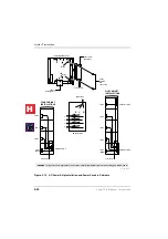
Page 365: ...rnal Music on Hold source SELV PDKU2A For connection of Toshiba proprietry terminals SELV PEKU2F For connection of Toshiba Visually Handicapped Console terminals TNV3 RSTU1F For connection of approved 2 wire devices TNV3 RSTU3F For connection of approved 2 wire devices TNV3 PCOU2F PCOUS2F For connection to PTO provided Loop Call Unguarded Clear exchange lines TNV1 RBSU2A 2 Cct ISDN2 CTR3 Basic Rat...

Page 366: ... B5CBU1F In accordance with safety requirements you are advised that in the event of these cells going faulty the entire unit must be returned to Toshiba Information Systems for correct disposal Under no circumstances must the cells be removed or replaced Type of Circuit EN60950 Classification Port Location Port Description SELV PIOU2A Contains various ports for connection of audio paging amplifie...

Page 367: ...eclares that the Strata CT product complies with the requirements of the EC Directive 1999 5 EC aka Radio Telecommunications Terminal Equipment directive A manufacture s Declaration under this Directive allows connection to the relevant Public Network Services and the right to place the Product on the market The Strata CT is classified as Call Routing Apparatus it is intended to be connected to th...

Page 368: ...cy Cadence Meaning Exchange Line Music On Hold N A Call on Hold DKT 1 500 640Hz modul 10Hz 2 1300 1780Hz modul 10Hz 3 860 1180Hz modul 10Hz 4 2000Hz mod by 10Hz 5 500Hz 6 1000 800Hz 7 1000 800Hz 8 660 500 9 2000Hz 1s On 3s Off 1s On 3s Off 1s On 3s Off 1s On 3s Off 1s On 3s Off 0 6s On 1000Hz 0 6s On 800Hz 0 6s On 1000Hz 0 6s 800Hz 0 7s On 660Hz 0 7s On 500Hz 1s On 3s Off I C PSTN call Opt 1 I C P...

Page 369: ...ff 0 375s On 0 375s Off 0 375s On 0 375s Off 1s On Dial Tone Ringing Tone Extension Tone NU Reorder Tone Executive override Table A4 Sys Port Type PCOU2F RBSU1A RPTU1F PEMU2F PACU2F RSTU3F to fm to fm to fm to fm to fm to fm PCOU2F 3 7 3 7 1 8 1 9 1 8 1 9 3 1 3 2 0 7 1 5 RPTU1F 1 9 1 8 0 0 0 0 RBSU2A 1 9 1 8 0 0 0 0 PEMU2F 3 1 3 2 1 3 1 3 1 3 1 3 2 6 2 6 2 0 2 0 PACU2F 0 7 1 5 3 4 2 5 3 4 2 5 2 0 ...

Page 370: ...Notes to Users A 6 Strata CT I M Manual October 2000 H C ...
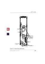
Page 371: ... electronic key and PBX systems BCU Represents all of the Strata CT processors The Strata CT processors are B1CU B2CAU B2CBU B3CAU B3CBU B5CAU B5CBU B2CAU BU Abbreviation for the B2CAU B2CBU B3CAU BU Abbreviation for the B3CAU B3CBU B5CAU BU Abbreviation for the B5CAU B5CBU B channel Used in ISDN Data or voice information is transmitted on the B channels of an ISDN line at 64kpbs The B channel ref...

Page 372: ... the stations and peripherals connected to the expansion cabinet PCBs As many as four expansion cabinets can be added to the system CLASS Custom Local Area Signalling Services Defines a number of features offered by local telephone companies CLI Calling Line Identification Telephone number of the calling party sent to the Strata CT system over incoming loop start Exchange lines CODECs Coder Decode...

Page 373: ...Unit An optional backup unit that provides emergency service during power failures by automatically connecting up to eight standard telephones to designated Exchange lines DSS Direct Station Selection Feature which allows a telephone user as well as a DSS console and ADM user to call another station with the touch of a flexible feature button DTMF Dual tone Multi frequency Push button tone diallin...

Page 374: ...eceive Off hook Call Announce OCA calls The telephone must be connected to an Electronic Telephone Interface Unit PEKU or a Standard Telephone Electronic Telephone Interface Unit PESU equipped with an Off hook Call Announce Subassembly EOCU to receive OCA and must have three pair wiring IMDU Remote Maintenance Modem Subassembly A subassembly installed on an Option Interface Unit PIOU or PIOUS that...

Page 375: ...rface units stand alone and integrated a digital DSS console DDSS RPCI ADM and a digital door phone lock control unit DDCB PDN Primary Directory Number PEKU Electronic Telephone Interface Unit An optional PCB that provides the system with eight electronic telephone circuits which can support electronic telephones a Background Music source a door phone lock control unit HDCB an electronic DSS conso...

Page 376: ... to four attendant consoles and or PC attendant consoles RBSU ISDN Basic Rate Interface BRI Unit Provides two circuits each of which provide two simultaneous voice and or data connections with a single interface BRI uses the 2B D transmission format which is defined as two 64 kbps bearer channels and one 16 kbps data control channel Available for Strata CT RBSS ISDN Basic Rate Interface BRI Subass...

Page 377: ...e Interface Unit An optional PCB an older version of RSTU2 with a built in ring generator that provides interface for eight standard telephones or optional hardware peripherals voice mail devices Background music source fax machines etc The RSTU has a built in 80V RMS sine wave ring generator The RSTU also has connectors for the R48S which extends station loop length and is described in this secti...

Page 378: ... V 35 or V 449 data interfaces TE Terminal Equipment This refers to devices using ISDN service telephones faxes computers etc TE1 supports ISDN formats with S T or U type intefaces TSPI Telephony Service Provider Interface TTY Flexible RS 232 port which can be used for maintenance SMDI and MIS ACD TTY PC CABLE Designed to connect directly to the DB9 connector of PC COM ports while PPTC connects di...

Page 379: ...ncer 6 50 B B1CU PCB 2 42 B2CAU PCB 2 43 B2CBU PCB 2 44 B3CAU PCB 2 45 B3CBU Controls Indicators and Interface Connectors 2 46 B3CBU PCB 2 46 B5CAU PCB 2 47 B5CBU PCB 2 48 background music see BGM BCU installation procedures 2 40 BCU PCBs 2 42 2 45 2 46 beep strap 5 14 5 20 BGM 6 3 alternate source installation 6 9 external installation 6 10 options 6 3 6 6 single page zone 6 28 to connect source ...

Page 380: ... 5 16 loud ringing bell headset 5 11 microphone speaker sensitivity adjustment 5 15 simultaneous voice data 5 8 TAPI 5 8 telephone speaker off hook call announce 5 4 digital telephone interface unit 3 7 direct station selection see DSS DISA 6 37 distributed hunt 1 6 DKT2000 ADM installation 5 16 DKT2510 strap connector locations 5 11 door lock control 6 10 DDCB HDCB 6 14 relay options 6 10 door lo...

Page 381: ...enance faults 8 15 station dial tone faults 8 10 voice mail auto attendant faults 8 13 functional block diagram 1 13 H handset OCA stations 1 7 HDSS console 3 10 connections 5 22 headset upgrade 5 11 HESB amplified speaker installation 6 22 installation test 6 22 external speaker unit 6 17 loud speaker amplification 6 17 installation for DKT 6 18 test 6 20 loud speaker amplification for EKT 6 20 t...

Page 382: ...U switches jumpers and connectors 10 5 SMDR output 6 35 timing and synchronisation 10 22 10 26 ISDN BRI RBSS PCB installation 10 14 RBSU RBSS capacity and cabinet slot information 10 10 PS 1 line power option 10 10 R40S PCB installation 10 14 L line capacities 1 4 lock control unit 5 23 loud ringing bell upgrade 5 11 headset upgrade 5 18 M MDFB 5 23 cabling 5 23 volume control 5 25 wall mounting 5...

Page 383: ...1 installation 3 19 programming 3 20 PDKU 3 7 hardware options 3 7 illustration 3 8 programming 3 7 PEKU 3 9 hardware options 3 9 illustration 3 11 installation 3 10 programming 3 10 PEMU connectors controls indicators 3 25 illustration 3 25 installation procedures 3 23 programming 3 24 PEPU 3 17 installation procedure 3 17 programming 3 18 peripherals installation 6 1 pickup groups 1 6 PIOU PIOUS...

Page 384: ...internal station call 6 37 DISA outgoing exchange line call 6 38 ring no answer DISA call 6 37 programming considerations 6 39 speaker OCA stations 1 7 speakerphone 5 15 5 21 speed dial system capacities 1 6 standard telephone 1 7 connecting to system 5 5 interface unit 3 35 station apparatus 5 1 telephones 5 1 station message detail recording see SMDR strap beep 5 14 5 20 carbon headset handset 5...

Page 385: ... PEMU 3 23 universal slots 1 7 V verified account codes 1 6 voice mail 6 41 options 6 41 program checklist 6 44 programming considerations 6 42 programming considerations general 6 43 SMDI 1 6 system installation 6 45 voice messaging customer supplied 6 43 Stratagy 6 41 W Windows 5 28 windows operator s console WOC 5 28 wiring diagram 2 wire tie line PEMU 4 16 4 wire tie line PEMU 4 17 exchange li...

Reviews: