Services
Strata Net Programming Overview
Strata CTX Programming - Part 2: CTX WinAdmin Programming 6/04
9-53
Ser
v
ic
es
Configuration
RPTU2 PCB
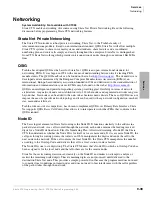
The Strata CTX uses a new Primary Rate Interface PCB that can terminate either a Strata Net connection
or a public PRI: the RPTU-2A. The RPTU-2A is backwardly compatible with the RPTU-1A for standard
ISDN operation. The mode of operation (standard or QSIG) is controlled by a programming parameter
named “Private Service Type.” This parameter must be chosen in establishing both incoming and OLGs.
Circuits
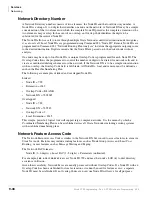
Two Strata Net nodes are connected to each other by a full or fractional DS1. The QSIG basic call
convention will select one DS0 to act as the “D” channel and the remainder as “B” channels. This allows
the interconnecting DS1(T-1) to act as a Primary Rate Interface. The appropriate command set is in new
firmware on the card to allow Strata CTX for signal according to CPE-to-CPE rules which differ from
CPE-to-PSTN rules. Fractional DS1s may consist of 8, 12 or 16 channels including the “D” channel.
The most common type of interconnection is a leased DS-1 from a Common Carrier such as the primary
telephone company or long distance provider. DS1s may also be created across fiber optics, Frame Relay
equipment, IP networks or other transport media using dealer-supplied equipment as long as they conform
to the following specifications.
•
1.544 MBPS
•
B8ZS
•
ESF
Nodes may also be connected directly over two copper pairs to a maximum distance of 738 feet. See the
Strata CTX Installation and Maintenance Manual
for pin configurations and other details.
Strata Net Programming Overview
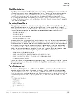
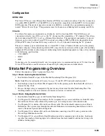
Follow the sequences below to program Strata Net.
Step 1:
Basic Incoming Network Calls
1. Establish the Node ID as part of the Flexible Numbering Plan (Program 102).
Note
Node ID is located under
01 Feature Name
as “Node ID (CTX network number prefix).”
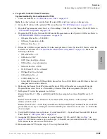
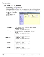
2. Establish up to four Local Node IDs (Program 656) for the primary node. Each Node ID can have a
unique Overlap Code.
3. Process the digit string as manipulated by the Overlap Code from Flexible Numbering Plan. The
resulting number can be an extension call, feature activation, or tandem call.
Step 2:
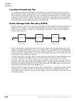
Basic Outgoing Network Calls
1. Establish the Node ID as part of 102 Flexible Numbering Plan.
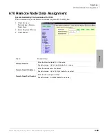
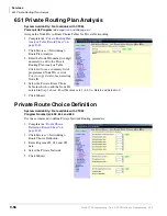
2. Use Program 651 Routing Plan Analysis Table Assignment to associate each Remote Node ID with a
Private Route Choice table which will provide up to six routing choices to the desired node.
3. Use Program 653 to define a Private Route Choice table. The table should contain up to six Route
Definitions. The system steps through these Route Definitions in terminating hunt fashion to find a
route to the desired private networking node.
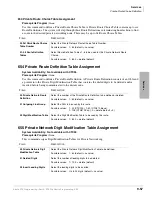
4. Use Program 654 to define a Private Route Definition consisting of an OLG and a pointer into the
Private Digit Modification table.
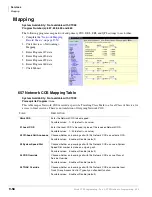
5. Use Program 655 to set up Private Digit Modification tables containing up to 64 entries. Each entry
specifies the number of leading digits to be deleted from the dialed number and the dial string to be
added as leading digits.
Summary of Contents for Strata CTX 100-S
Page 20: ......
Page 40: ......
Page 324: ......
Page 445: ...726 Digital Solutions Division June 2004 Part 4 Appendices Digital Business Telephone Systems ...
Page 446: ......
Page 574: ...Record Sheets Services D 56 Strata CTX Programming Part 4 Appendices 6 04 ...

