


5-5
INSTALLATION-KSU
SECTION 400-096-205
SEPTEMBER 1992
-24V
-5V
+5V
-24V
-24V
DG
FG
1
2
2
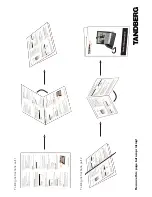
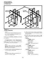
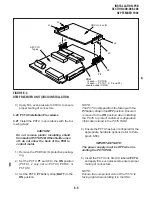
4.22 DK56/96. Refer to Figure 5-4 or 5-5, and
replace the power supply in accordance with the
following steps:
1) Slide the new power supply into the opening in
the KSU.
2) Align the mounting screw holes on the power
supply’s front panel with the holes in the KSU's
power supply mounting bracket.
3) Secure the power supply with the four combina-
tion slotted/Phillips screws.
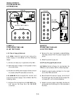
4) Insert the DC OUT cable plug into the DC OUT
connector (this is a keyed plug that can only be
inserted one way). Insert the plug into the
connector until its locking tab engages.
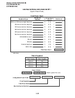
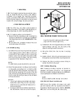
5 CIRCUIT BREAKER DISTRIBUTION
5.00 Refer to Fault Finding, Section 400-096-500,
Tables B, C, and D for circuit breaker distribution.
6 VOLTAGE TROUBLESHOOTING
6.00 Refer to Fault Finding, Section 400-096-500,
Paragraph 6, for voltage troubleshooting.
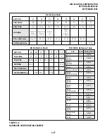
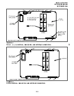
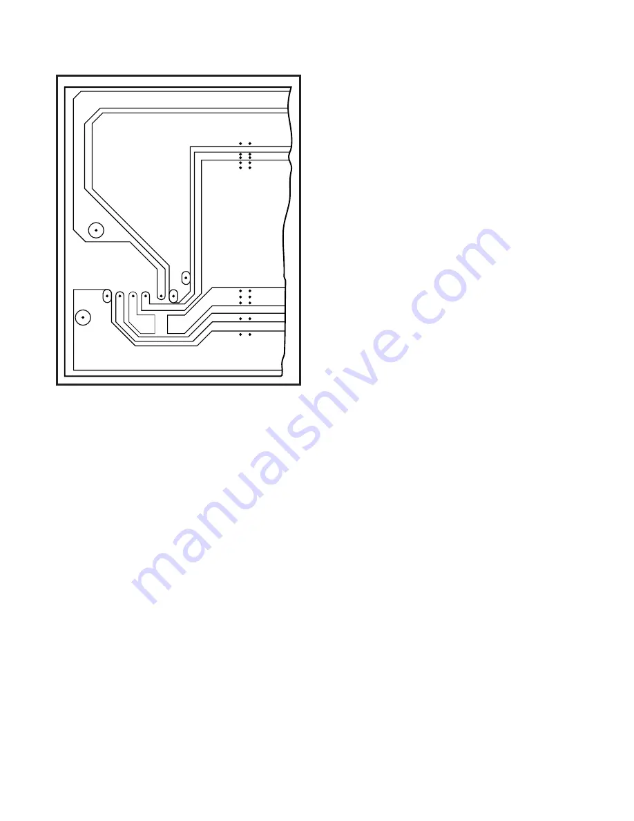
FIGURE 5-6
LOWER LEFT OF DK24 BACKPLANE PCB
(PMB-824)
Summary of Contents for Strata DK 24
Page 2: ......
Page 10: ......
Page 12: ...INSTALLATION SYSTEM DESCRIPTION SECTION 400 096 202 SEPTEMBER 1992 ...
Page 42: ......
Page 72: ......
Page 102: ......
Page 110: ......
Page 144: ...INSTALLATION TELEPHONE SECTION 400 096 207 SEPTEMBER 1992 ...
Page 164: ......
Page 166: ...INSTALLATION PERIPHERALS SECTION 400 096 208 SEPTEMBER 1992 ...
Page 170: ......
Page 238: ...INSTALLATION WIRING DIAGRAMS SECTION 400 096 209 SEPTEMBER 1992 ...
Page 300: ......
Page 302: ...REMOTE ADMINISTRATION MAINTENANCE PROCEDURES SECTION 400 096 600 SEPTEMBER 1992 ...
Page 372: ......