8
1
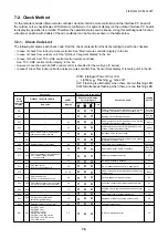
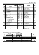
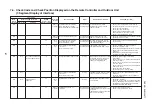
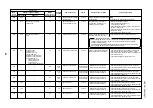
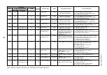
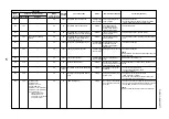
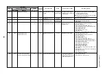
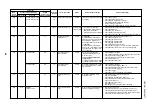
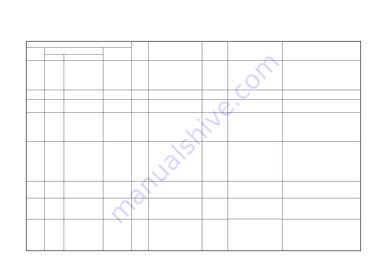
7-4. Check Code and Check Position Displayed on the Remote Controller and Outdoor Unit
(7-Segment Display of Interface)
Check code
Main
remote
controller
E01
E02
E03
E04
E06
—
E08
E09
Outdoor 7-segment display
Check code
Sub-code
—
—
—
—
—
—
—
—
E06
No. of indoor units which
received signal normally
E07
—
E08
Duplicated indoor
addresses
—
—
AI-NET
central control
remote controller
—
—
97
4
4
—
96
99
Detected
position
Remote
controller
Remote
controller
Indoor
unit
Indoor
unit
I/F
I/F
Indoor
I/F
Remote
controller
Check code name
Communication error between
indoor and remote controller
(Detected at remote controller side)
Remote controller sending error
Communication error between
indoor and remote controller
(Detected at indoor side)
Indoor/outdoor communication
circuit error
(Detected at indoor side)
Decreased number of indoor units
Indoor/outdoor communication
circuit error
(Detected at outdoor side)
Duplicated indoor addresses
Duplicated master remote
controllers
Status
Corresponding
unit only stops.
Corresponding
unit only stops.
Corresponding
unit only stops.
Corresponding
unit only stops.
All stop
All stop
All stop
Corresponding
unit only stops.
Error detection condition
Communication interrupted
between indoor P.C. board and
remote controller.
Signal could not be sent from
remote controller to indoor unit.
No communication from remote
controller (including wireless) and
communication adaptor.
Indoor unit does not receive
communication from outdoor unit.
When signal is not sent for a certain
period from the indoor unit which
has been used to send signals,
[E06] is normally displayed.
Transmission from outdoor to indoor
cannot continue for 30 seconds.
Multiple indoor unit address setup
are duplicated.
In 2-remote controller control
(including wireless), both are setup
as master
(Header indoor unit stops and other
indoor unit is operating.)
Check item (position)
• Check remote controller inter-unit wire (A/B).
• Check disconnection, connector contact error.
• Check indoor power supply.
• Check indoor P.C. board error.
• Check remote controller address setup.
(When two remote controllers operate)
• Check remote controller P.C. board.
• Check the communication wire of remote controller:
Exchange remote controller.
• Check remote controller and communication
adaptor wiring.
• Check power-ON order of indoor/outdoor.
• Check indoor address setup.
• Check inter-unit wiring between indoor and outdoor.
• Check outdoor end terminal resistance setup
(SW30-2).
• Check SW02 setup on the wall type P.C. board.
(Should be Bit 1: ON, Bit 2: OFF)
• Check the power supply of indoor unit.
(Power-ON)
• Check connection of communication line between
indoor and outdoor.
• Check connector connection for communication in
indoor P.C. board.
• Check connector connection for communication in
outdoor P.C. board.
• Check indoor P.C. board failure.
• Check outdoor P.C. board (I/F) failure.
• Check outdoor end terminal resistance setup
(SW30-2).
• Check the communication connection between
indoor and outdoor.
• Check indoor address.
• Check the change of remote controller connection
(Group / individual) after setup of indoor address.
• Check SW02 setup on the wall type P.C. board.
(Should be Bit 1: ON, Bit 2: OFF)
• Check remote controller setup.
• Check remote controller P.C. board.
FILE NO. SVM-1
40
77


