8
7
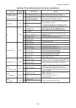
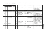
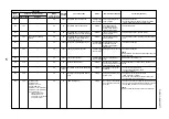
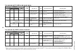
Check code
Main
remote
controller
L03
L04
L05
L06
L07
L08
L09
L10
L20
L28
L29
Outdoor 7-segment display
Check code
Sub-code
—
—
L04
—
—
—
L06
No. of indoor units with
priority
—
—
L08
—
—
—
L10
—
—
—
L28
—
L29
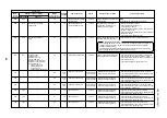
01: IPDU1 error
02: IPDU2 error
03: IPDU1, 2 errors
04: Fan IPDU error
05: IPDU1 + Fan IPDU error
06: IPDU2 + Fan IPDU error
07: All IPDU error or
communication error
between IPDU and
I/F P.C. board, or outdoor
I/F P.C. board error
AI-NET
central control
remote controller
96
96
96
96
99
99
46
88
98
46
CF
Detected
position
Indoor
I/F
I/F
I/F
Indoor
Indoor
Indoor
I/F
AI-NET,
Indoor
I/F
I/F
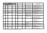
Check code name
Duplicated indoor center units
Duplicated outdoor line address
Duplicated indoor units with priority
(Displayed on indoor unit with priority)
Duplicated indoor units with priority
(Displayed on the unit other than
indoor unit with priority)
Group line in individual indoor unit.
Indoor group / address unset
Indoor capacity unset
Outdoor capacity unset
Duplicated central control addresses
Quantity over of connected outdoor
units
IPDU quantity error
Status
Corresponding
unit only stops.
All stop
All stop
All stop
Corresponding
unit only stops.
Corresponding
unit only stops.
Corresponding
unit only stops.
All stop
All stop
All stop
All stop
Error detection condition
There are multiple center
units in a group.
Line address setup is
duplicated against the
outdoor unit in different
refrigerant pipe system.
Indoor units with priority
were duplicated.
Indoor units with priority
were duplicated.
At least one indoor unit
connected to a group
existed in the individual
indoor units.
Address was not yet set up.
Indoor unit capacity was
unset.
On the I/F P.C. board for
service, jumper line was not
cut according to the model.
Duplicated central control
addresses
There were more than four
outdoor units.
No. of IPDU units detected
when power was turned on
were less.
Check item (position)
• Check indoor address.
• Check the change of remote controller connection
(Group/individual) after indoor address setup.
• Check line address.
• Check display of indoor unit with priority.
• Check display of indoor unit with priority and outdoor
unit.
• Check indoor address.
• Check indoor address.
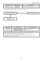
[Note]
After installation, this code is displayed when the power
is firstly turned on.
Set up indoor capacity. (DN=11)
Check model setup on outdoor I/F P.C. board A’ssy for
service.
• Check central control address.
• Check network adaptor P.C. board.
(In case of AI-NET)
• Check No. of connected outdoor units.
(Max. 4 units per 1 system)
• Check communication line between outdoor units.
• Check outdoor P.C. board (I/F) error.
• Check model setup for outdoor I/F service P.C. board.
• Check connection of UART communication connector.
• Check IPDU, fan IPDU, and I/F P.C. board error.
[Note]
UART: Universal Asynchronous Receiver Transmitter.
FILE NO. SVM-1
40
77


