

T1960CS/T1960CT
1-1
1.1
Features
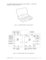
The Toshiba T1960CS and T1960CT are two of the lightest and most advanced portable
computers available. Utilizing advanced technology and high-speed components, the
T1960CS/T1960CT offer excellent display legibility, battery operation and IBM PC/AT
compatibility. The T1960 Series of computers consist of the following features:
❑
Microprocessor
The SL Enhanced Intel 486DX2-50 microprocessor operates at 50 MHz, 3.3 Volts.
❑
Math co-processor
A math co-processor is stored in the i486DX2 microprocessor.
❑
Cache memory
8 KB of cache memory is stored in the i486DX2 microprocessor.
❑
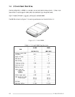
Disk storage
The internal 200 Megabyte (MB) Hard Disk Drive (HDD) has an average access time
of 13 milliseconds, while the 320 MB HDD has an average of 12 milliseconds. The
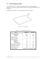
3.5-inch Floppy Disk Drive (FDD) supports 2HD floppy disks (1.44 MB) and 2DD
floppy disks (720 Kbytes).
❑
Memory
The T1960CS/T1960CT comes standard with 4 MB of CMOS Random Access
Memory (RAM) 3.3 Volts. This includes 640 KB of conventional memory and 3,456
KB of extended memory which can be utilized as expanded memory compatible with
the Lotus/Intel/Microsoft Expanded Memory Specifications (LIM-EMS).
❑
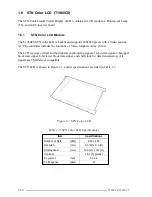
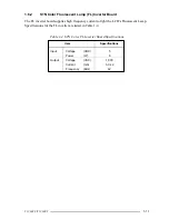
STN color LCD (T1960CS)
The high-resolution, Supertwist Nematic (STN) color Liquid Crystal Display (LCD)
displays 640x480 pixels with 226,981 colors for both graphics and characters. The
T1960CS internal display controller supports Video Graphics Array (VGA) functions
on the internal display devices.
❑
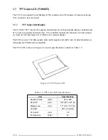
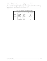
TFT color LCD (T1960CT)
The high-resolution, Thin Film Transistor (TFT) color LCD displays 640x480 pixels
with 262,144 colors for both graphics and characters. The T1960CT internal display
controller supports VGA functions for internal display and Super VGA (SVGA) for
external display.
Summary of Contents for T1960CS
Page 20: ...T1960CS T1960CT 2 3 Figure 2 1 Troubleshooting Flowchart 1 2 ...
Page 154: ...B 2 T1960CS T1960CT Figure B 2 FA2SU FA2PU System Board back ...
Page 156: ...B 4 T1960CS T1960CT B 2 FA2SL System Board Figure B 3 FA2SL System Board front ...
Page 157: ...T1960CS T1960CT B 5 Figure B 4 FA2SL System Board back ...
Page 169: ...T1960CS T1960CT D 1 Appendix D USA Display Codes Table D 1 USA Display Codes ...


