


T1960CS/T1960CT
2-7
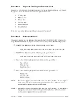
Procedure 3
PCB Replacement Check
The power supply is mounted on the lower system board (FA2SL*). If either the power
supply or the system board is damaged, refer to Chapter 4 for instructions on how to disas-
semble the T1960CS/T1960CT, then perform the following checks.
Check 1
Replace the lower system board with a new one and restart the system. If the
problem still exists, go to Check 2.
Check 2
Replace the upper system board with a new one and restart the system. If the
problem still exists, other FRUs may be damaged.
Summary of Contents for T1960CS
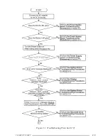
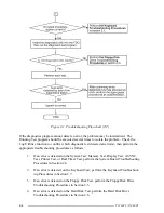
Page 20: ...T1960CS T1960CT 2 3 Figure 2 1 Troubleshooting Flowchart 1 2 ...
Page 154: ...B 2 T1960CS T1960CT Figure B 2 FA2SU FA2PU System Board back ...
Page 156: ...B 4 T1960CS T1960CT B 2 FA2SL System Board Figure B 3 FA2SL System Board front ...
Page 157: ...T1960CS T1960CT B 5 Figure B 4 FA2SL System Board back ...
Page 169: ...T1960CS T1960CT D 1 Appendix D USA Display Codes Table D 1 USA Display Codes ...


