TA8266HQ
2006-04-28
5
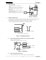
4. AUX
Input
(pin 16)
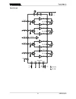
The pin 16 is for input terminal of AUX
amplifier.
The total gain is 0dB by using of AUX amplifier.
Therefore, the
µ
-COM can directly drive the
AUX amplifier.
BEEP sound or voice synthesizer signal can be
input to pin 16 directly.
When AUX function is not used, this pin must be
connected to PRE-GND (pin 13) via a capacitor.
5.
Diagnosis Output
(pin 25)
This diagnosis output terminal of pin 25 has open collector output structure on chip as shown in Figure 7.
In case diagnosis circuit that detect unusual case is operated, NPN transistor (Q1) is turned on.
It is possible to protect all the system of apparatus as well as power IC protection.
In case of being unused this function, use this IC as open-connection on pin 25.
5.1
In Case of Shorting Output to V
CC
/GND or Over Voltage Power Supplied
NPN transistor (Q1) is turned on.
Threshold of over voltage protection: VCC
=
22 V (typ.)
5.2
In Case of Shorting Output to Output
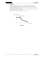
NPN transistor (Q1) is turned on and off in response to the input signal voltage.
25
5 V
LED/LCD
ALARM
REGULATOR
→
OFF
(Flashing)
(Announcement from a speaker.)
(Relay
→
OFF)
µ
-COM
MEMORY (Count and record)
Figure 8 Application 1
Figure 6 AUX Input
20dB AMP.
IN
OUT (
+
)
OUT (
−
)
16
AUX-IN
−
20dB
AUX AMP
µ
-COM
Figure 7 Self Diagnosis Output
pin 25: Open collector output (active low)
OUTPUT SHORT
PROTECTOR
OVER VOLTAGE
PROTECTOR
25
Q1
5 V
Q1 is turned on
GND
5 V
t


