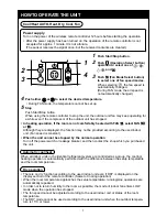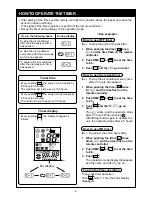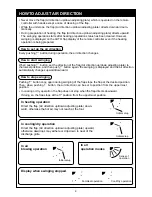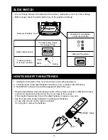
3
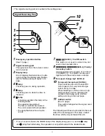
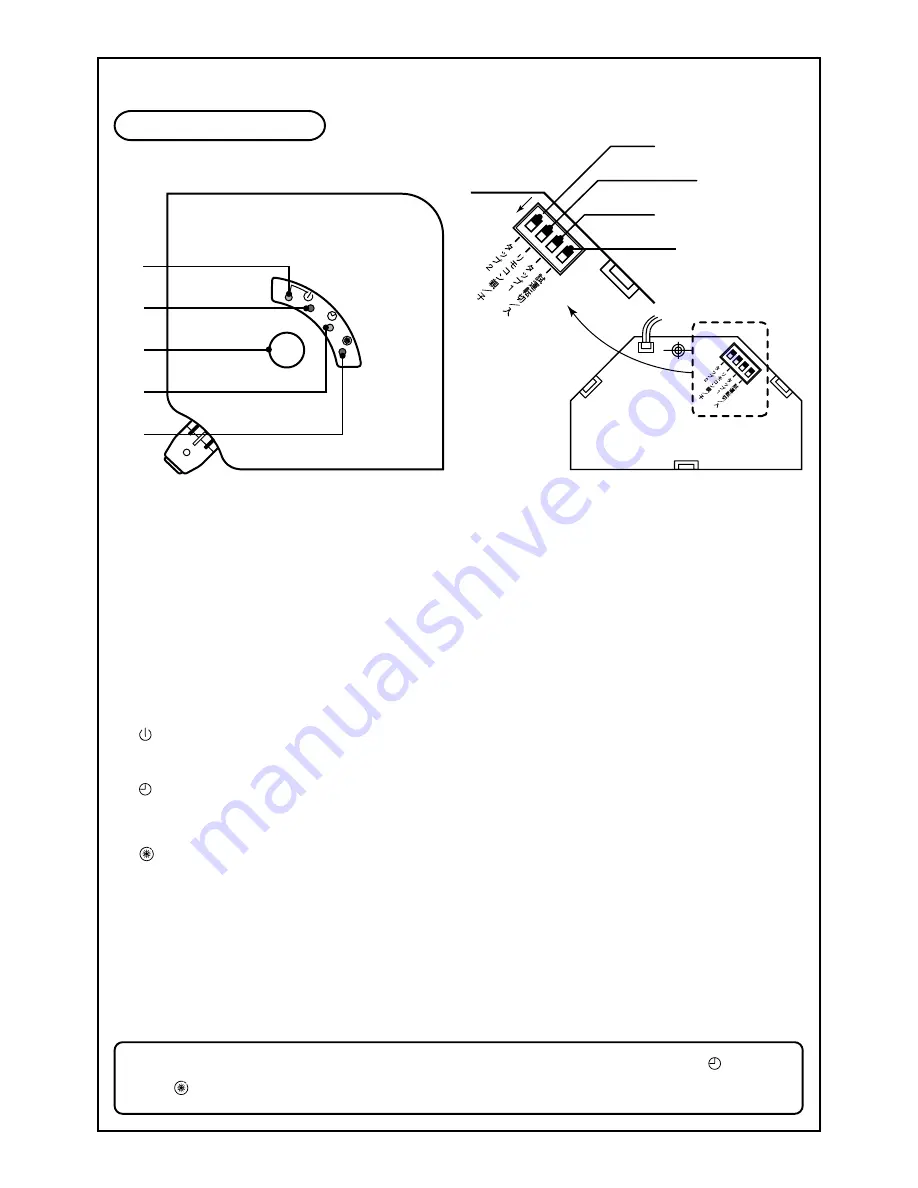
• The signal receiving part is mounted to the ceiling panel.
Signal Receiving Part
1
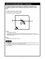
Emergency operation button
(See 13 page.)
2
Signal receiving part
The signal sent from the remote control-
ler is received.
3
Display lamp
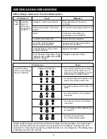
One of displays flashed while a trouble
occurs. When the display lamp flashes,
refer to “Before asking of repair” in 14
page.
4
lamp
This lamp goes on during operation.
5
lamp
This lamp goes on while the timer is
reserved.
6
lamp
• In heating operation this lamp in the
following cases;
The operation has started.
The temp. controller has worked.
The unit is under defrost operation.
• This lamp flashes while a trouble
occurs.
7
試運転
試運転
試運転
試運転
試運転
入
入
入
入
入
(S003-1) Trial ON switch
This switch is not used in normal time, but
used in trial operation time.
8
リモコン親
リモコン親
リモコン親
リモコン親
リモコン親 /
//
// リモコン子
リモコン子
リモコン子
リモコン子
リモコン子
(S003-3) Priority/
Secondary switch
Use this switch at the position of
[リモコン
親
(PRIORITY)
]
. This switch can be used
together with the wired remote controller.
9
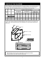
Fan speed change tap 1 (S003-2)
10
Fan speed change tap 2 (S003-4)
These switches are used to select DC
motor speed of a 4-way cassette type
indoor unit by the taps.
When installing an indoor unit to a high
ceiling surface or when changing the
number of discharge ports, perform
setting referring to the next page.
11
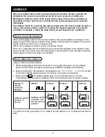
Address switch
(See 12 page.)
This switch distinguishes the signal, send
or receive.
The following switches are provided to the rear
side of the receiving part. For setup, contact
the shop which you purchased the unit.
• If “pi, pi” sound is heard, the MODE lamp of the display lamp goes on, and the
lamp
and
lamp flash alternately, the operation is not performed with the desired mode.
8
10
7
9
4
1
5
2
3
1
2
3
4
ON
S003
ON
1
2
3
4
ON
S003
ON


