1
INSTALLATION MANUAL
Digital Inverter Air Conditioner
“1 : 1 Model” Connection Interface
Use for Indoor Unit Only
MODEL : TCB-PCNT30TLE2
[For Installation Professionals]
• Before installation work, please read this manual thoroughly and install the products correctly.
Precaution for safety
WARNING
• Ask an authorized dealer or qualified installation professional to install/maintain the air conditioner.
Inappropriate installation may result in water leakage, electric shock or fire.
• Perform installation work surely based on this Installation Manual.
Incomplete installation causes an electric shock or a fire.
• Ask an authorized dealer or qualified installation professional to reinstall 1 : 1 Model Connection
Interface.
Incomplete installation causes an electric shock or a fire.
• For an electric work, this Installation Manual shall be referred and exclusive circuit shall be
necessarily used. The used voltage shall be also match with the rated voltage of the product.
If there is capacity shortage of electric circuit or installation work is poor, an electric shock or a fire may be
caused.
CAUTION
• Using the specified wires, surely connect wires so that external force of wire is not applied to connecting
part of the terminals; otherwise disconnection, heating or fire will generate.
• For wiring work, use wires with correct current capacity; otherwise leakage, heating or fire will generate.
• Do not apply an excessive force on the board body, otherwise bending, separation, or disconnection gener-
ates resulted in heating or fire.
• After installation work, execute a test run to confirm there is no trouble.
And also ask the customers to keep this Manual by themselves.
Components
* When you will purchase the 4-way cassette type (RAV-SM
∗∗
4UT
∗
) or you will also purchase the compact 4-
way cassette type (RAV-SM
∗∗∗
MUT
∗
), be sure to purchase “TCB-PX30MUE” sold separately, together with it.
For installation, 1:1 Model Connection Interface board box of “TCB-PX30MUE” is necessary.
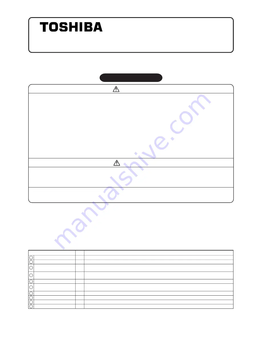
Name
Q’ty
Application
P.C. board
1
1
1 : 1 model connection interface board
Installation Manual
1
5
This manual
Spacer (B)
1
7
For fixing “1 : 1 Model” Connection Interface board (Required according to shape of indoor unit)
Screws to fix terminal block
2
8
For fixing relay terminal block (M4 × 14L)
Bandling band
3
9
Used to process wires
Terminal nameplate
1
10
To be adhered near the relay terminal block
U3, U4 terminal block
1
2
2P terminal block for relay (U3, U4)
Relay wire (A)
1
3
For connection of “1 : 1 Model” Connection Interface board with U3, U4 relay terminal block
(Blue connector)
Relay wire (B)
1
4
For connection of “1 : 1 Model” Connection Interface board with indoor control board
(Red connector)
Spacer (A)
3
6
For fixing “1 : 1 Model” Connection Interface board
(Used when installing P.C. board on sheet metal of the electric parts box of indoor unit)

